Mitsubishi Colt Ralliart. Manual — part 411

SYMPTOM PROCEDURES
SMART WIRING SYSTEM (SWS) USING SWS MONITOR
54C-152
INSPECTION PROCEDURE J-6: The high-beam indicator lamp does not illuminate.
CAUTION
Whenever the ECU is replaced, ensure that the
input and output signal circuits are normal.
COMMENTS ON TROUBLE SYMPTOM
If the high beam indicator does not illuminate nor-
mally, connector(s), wiring harness in the CAN bus
lines, the ETACS-ECU or the combination meter may
be defective.
POSSIBLE CAUSES
• Malfunction of the combination meter
• Malfunction of the ETACS-ECU
• Damaged harness wires and connectors
DIAGNOSIS PROCEDURE
Step 1. Check the headlamps.
When the lighting switch is operated, check that the
headlamps illuminate/go off normally.
Q: Are the headlamps in good condition?
YES :
Go to Step 2.
NO :
First, repair the headlamps. Refer to
Inspection Procedure J-3 "The high-beam
headlamps do not illuminate normally
."
Step 2. M.U.T.-III CAN bus diagnostics.
Use the M.U.T.-III to diagnose the CAN bus lines.
Q: Is the check result normal?
YES :
Go to Step 3.
NO :
Repair the CAN bus line (Refer to GROUP
54D, Diagnosis
).
Step 3. M.U.T.-III other system diagnosis code.
Check whether the combination meter-related diag-
nosis code is set.
Q: Is the diagnosis code set?
YES :
Diagnose the combination meter (Refer to
GROUP 54A
− Troubleshooting
NO :
Go to Step 4.
Step 4. ECU check by using the SWS monitor
Check that the power supply and earth lines to the
ETACS-ECU and the SWS communication lines are
normal.
• Ignition switch: OFF
ECU TO BE CHECKED
• ETACS ECU
OK: "OK" is displayed on the "ETACS ECU"
menu.
Q: Is the check result normal?
YES :
Go to Step 5.
NO :
Refer to Inspection Procedure A-3
"Communication with the ETACS-ECU is
not possible
INPUT SIGNAL
ETACS-ECU
DIMMER SWITCH
COMBINATION
METER
CAN COMMUNICATION LINE
(CAN_L LINE)
CAN COMMUNICATION LINE
(CAN_H LINE)
High-Beam Indicator Lamp Circuit
Main
Index
Group
TOC

SYMPTOM PROCEDURES
SMART WIRING SYSTEM (SWS) USING SWS MONITOR
54C-153
Step 5. M.U.T.-III actuator test
Perform the actuator test for the combination meter,
and check that the high-beam indicator illuminates
(Refer to GROUP 54A
− Combination Meter
).
Q: Is the check result normal?
YES :
Replace the ETACS-ECU.
NO :
Replace the combination meter.
Main
Index
Group
TOC

SYMPTOM PROCEDURES
SMART WIRING SYSTEM (SWS) USING SWS MONITOR
54C-154
INSPECTION PROCEDURE J-7: Any of tail lamps, position lamps or licence plate lamp does not
illuminate.
CAUTION
Whenever the ECU is replaced, ensure that the
input and output signal circuits are normal.
COMMENTS ON TROUBLE SYMPTOM
If the tail lamps, the position lamps or the licence
plate lamps do not illuminate, the wiring harness con-
nector(s), the bulb or the fuse may be defective or
burned out.
POSSIBLE CAUSES
• Burned-out bulb
• Damaged harness wires and connectors
FRONT
COMBINATION
LAMP
(POSITION: LH)
REAR
COMBINATION
LAMP (TAIL: LH)
ETACS-ECU
LICENCE
PLATE
LAMP
FRONT
COMBINATION
LAMP
(POSITION: RH)
TAIL LAMP RELAY
REAR
COMBINATION
LAMP (TAIL: RH)
J/B SIDE
Tail Lamps, Position Lamps and Licence Plate Lamp Circuit
Wire colour code
B : Black LG : Light green G : Green L : Blue W : White Y : Yellow SB : Sky blue
BR : Brown O : Orange GR : Grey R : Red P : Pink V : Violet PU : Purple
Main
Index
Group
TOC
SYMPTOM PROCEDURES
SMART WIRING SYSTEM (SWS) USING SWS MONITOR
54C-155
DIAGNOSTIC PROCEDURE
Step 1. Connector check: E-12 rear combination
lamp (tail: LH) connector or E-03 rear
combination lamp (tail: RH) connector, A-12 front
combination lamp (position: LH) connector or
A-25 front combination lamp (position: RH)
connector or E-07 licence plate lamp (LH)
connector
Q: Is the check result normal?
YES :
Go to Step 2.
NO :
Repair the defective connector.
Step 2. Check the bulbs of the tail lamps, the
position lamps or the licence plate lamps.
Check the bulb of the lamp which does not illumi-
nate.
Q: Is the check result normal?
YES :
Go to Step 3.
NO :
Replace the bulb of the lamp which does not
illuminate.
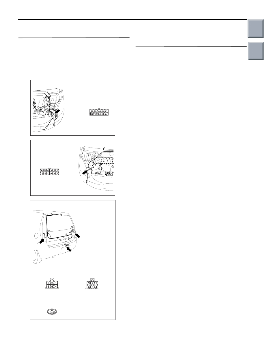
AC509191
Connector: A-12
Harness side
AB
A-12 (B)
AC509176
Connector: A-25
Harness side
AC
A-25(B)
AC401047
Connectors: E-03, E-07, E-12
Harness side
E-03
AB
E-03(B)
E-07
E-12(B)
Harness side
E-12
Harness side
E-07
Main
Index
Group
TOC
Нет комментариевНе стесняйтесь поделиться с нами вашим ценным мнением.
Текст