Mitsubishi Colt Ralliart. Manual — part 644

HYDRAULIC UNIT
ACTIVE STABILITY CONTROL SYSTEM (ASC)
35C-121
HYDRAULIC UNIT
REMOVAL AND INSTALLATION
M1357002000016
CAUTION
• Be careful when removing the hydraulic unit because it is heavy.
• Never loosen the nuts and the bolts because the hydraulic unit cannot be disassembled.
• Do not drop or shock the hydraulic unit.
• Do not place the hydraulic unit upside down or transversely.
Pre-removal operation
• Brake fluid draining
• Air cleaner body assembly removal (Refer to GROUP 15 −
Air Cleaner
.)
• Fuel Vapour Canister Removal
(Refer to GROUP 17
− Canister
Post-installation operation
• Fuel Vapour Canister Installation
(Refer to GROUP 17
− Canister
.)
• Air cleaner body assembly installation (Refer to GROUP
15
− Air Cleaner
.)
• Brake fluid refilling and air bleeding (Refer to GROUP 35A
− On-vehicle Service, Basic Brake System Bleeding
• Hydraulic Unit Check (Refer to
AC600665AB
15 ± 2 N·m
2
1
5
6
3
7
8 ± 2 N·m
2
4
4
2
2
Removal steps
1.
ASC-ECU harness connector
>>
A
2.
Brake tube connection
3.
Fuel vapour canister bracket
4.
Connection of brake tube and
clip
5.
Hydraulic unit (ASC-ECU)
6.
Hydraulic unit bracket insulator
7.
Hydraulic unit bracket
Removal steps (Continued)
Main
Index
Group
TOC

HYDRAULIC UNIT
ACTIVE STABILITY CONTROL SYSTEM (ASC)
35C-122
INSTALLATION SERVICE POINTS
>>A<< BRAKE TUBE INSTALLATION
Install each brake tube according to the colour of the
flare nut as shown.
AC601030AB
Yellow
Green
Yellow
Main
Index
Group
TOC

WHEEL SPEED SENSOR
ACTIVE STABILITY CONTROL SYSTEM (ASC)
35C-123
WHEEL SPEED SENSOR
REMOVAL AND INSTALLATION
M1357002200010
CAUTION
The wheel speed detection magnetic encoder collects metallic particles easily, because it is magnet-
ised. Inspect the wheel speed detection magnetic encoder for foreign material adhesion, and verify
that there is no malfunction in the encoder before assembly.
NOTE:
.
•
The encoder for detecting front wheel speed is a non-disassemble part integrated with the wheel bearing.
•
The encoder for detecting rear wheel speed is a non-disassemble part press fitted to the rear hub inner
ring.
INSTALLATION SERVICE POINTS
>>A<< ABS SENSOR PROTECTOR
INSTALLATION
Align the end of the white marking of the front wheel
speed sensor with the edge of the front wheel speed
sensor protector as shown in the figure.
INSPECTION
M1357002300017
Refer to GROUP 35B
− Wheel speed sensor.
AC600670AB
1
2
2
3
5
4
Front wheel speed sensor
removal steps
>>
A
<<
1.
Wheel speed sensor protector
2.
Front wheel speed sensor
3.
Wheel speed sensor bracket
Rear wheel speed sensor
removal steps
4.
Clip
5.
Rear wheel speed sensor
AC600671AB
Wheel speed
sensor protector
Front wheel
speed sensor
White mark
Main
Index
Group
TOC
G AND YAW LATE SENSOR
ACTIVE STABILITY CONTROL SYSTEM (ASC)
35C-124
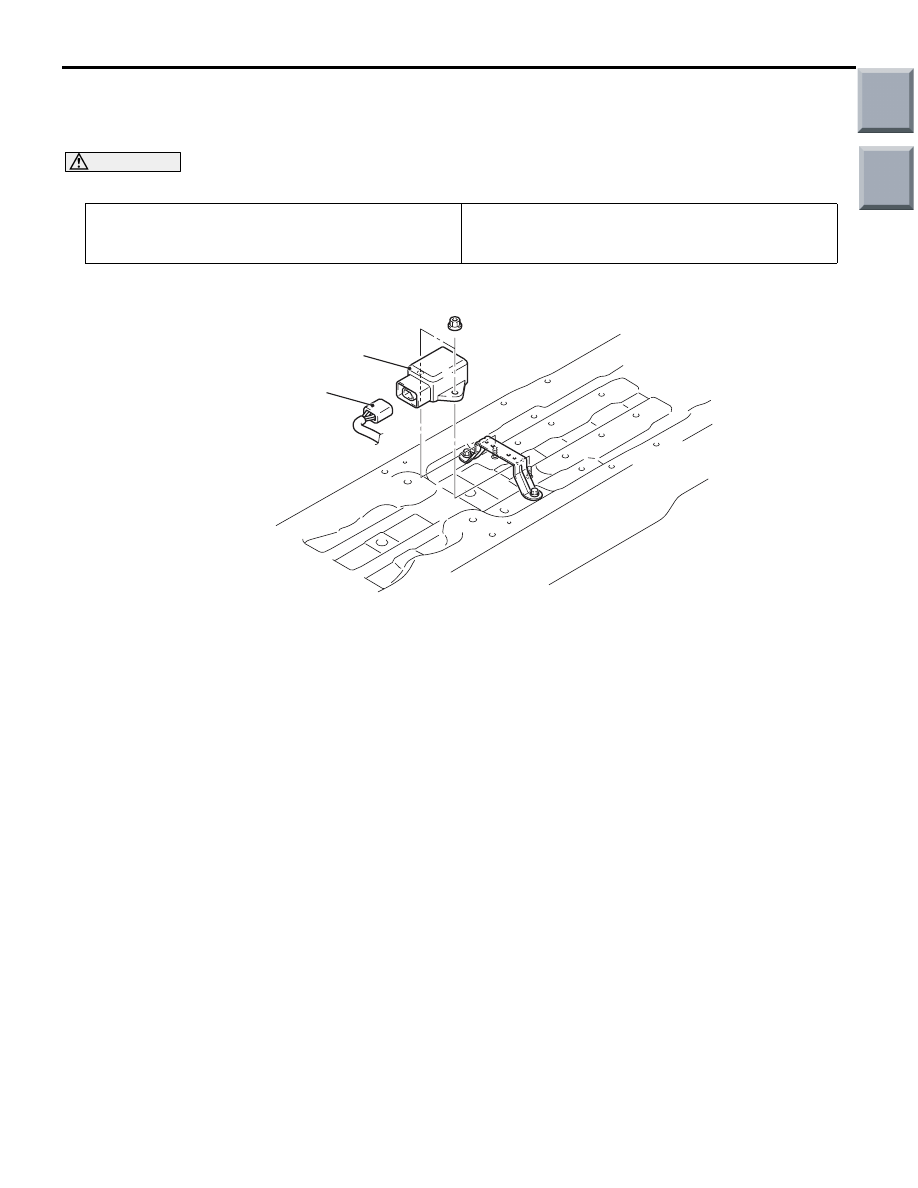
G AND YAW LATE SENSOR
REMOVAL AND INSTALLATION
M1357002500011
CAUTION
Do not drop or shock the G and yaw rate sensor.
Pre-removal operation
• Floor Console Assembly Removal (Refer to GROUP 52A
− Floor Console Assembly
Post-installation operation
• Floor Console Assembly Installation (Refer to GROUP
52A
− Floor Console Assembly
.)
AC600993AB
1
2
Removal steps
1.
Harness connector
2.
G and yaw rate sensor
Main
Index
Group
TOC
Нет комментариевНе стесняйтесь поделиться с нами вашим ценным мнением.
Текст