Mitsubishi Colt Ralliart. Manual — part 703
TROUBLESHOOTING
MULTIPORT FUEL INJECTION (MPI) <4G1>
13B-137
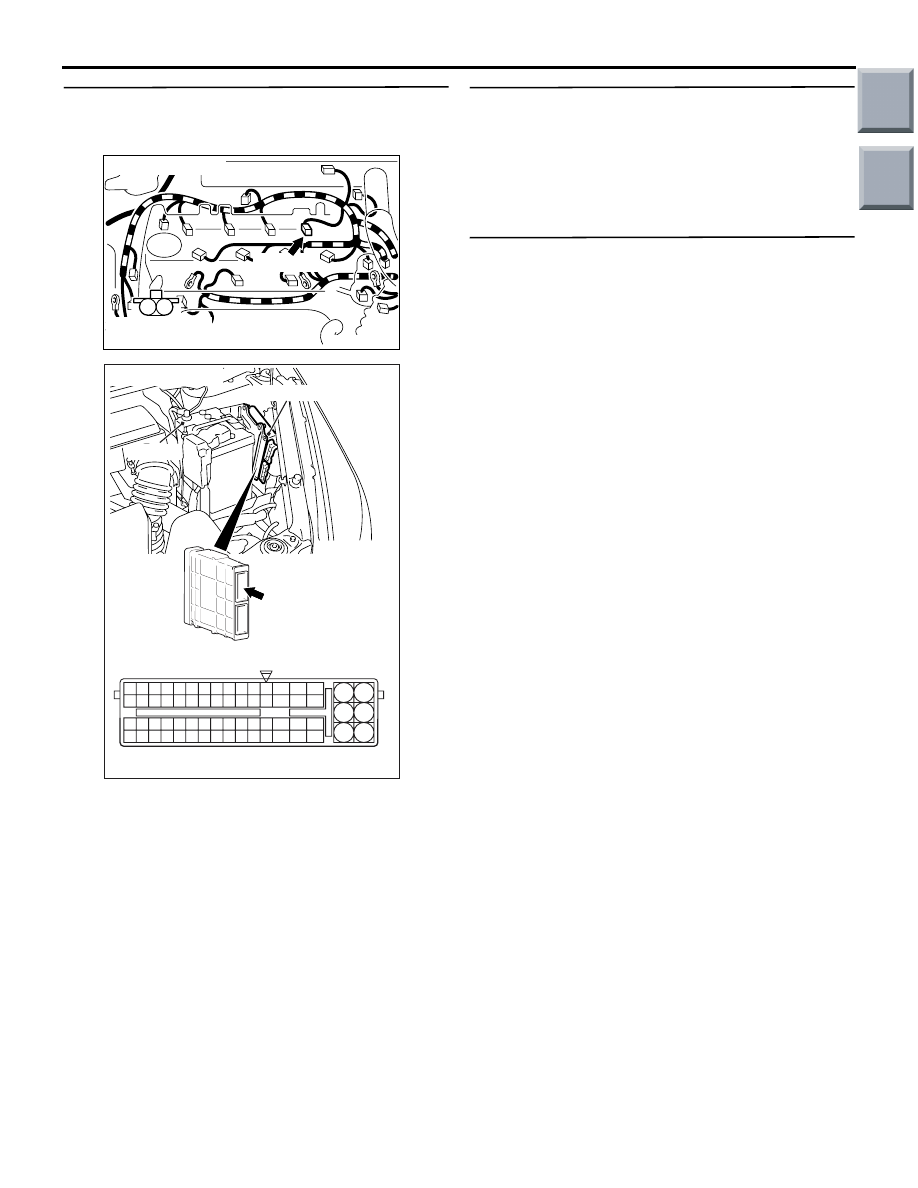
STEP 6. Check harness between A-105 (terminal
No. 2) No. 4 injector connector and A-114
(terminal No. 24) engine-ECU connector.
• Check earthing line for damage.
Q: Is the check result normal?
YES :
Go to Step 7 .
NO :
Repair the damaged harness wire.
STEP 7. Fuel pressure measurement.
• Fuel pressure measurement (Refer to Fuel Pres-
sure Test
Q: Is the check result normal?
YES :
Go to Step 8 .
NO :
Repair the fuel pressure.
STEP 8. M.U.T.-III diagnosis code.
• Reconfirmation of diagnosis code.
Q: Is the diagnosis code set?
YES :
Replace engine-ECU.
NO :
Intermittent malfunction (Refer to GROUP
00
− How to Use
Troubleshooting/Inspection Service Points
−
How to Cope with Intermittent Malfunctions
).
AK402091
M
1
2
A-105(G)
AC
Connector: A-105
Harness side
connector
AK402745
6
4
2
5
3
1
9
7
8
10
11
12
13
14
15
16
17
18
19
20
21
22
23
24
25
26
27
28
29
30
31
32
33
34
35
36
37
38
39
40
41
42
43
44
45
46
47
48
49
50
51
52
53
54
55
56
57
58
59
60
61
62
63
64
65
66
L
AF
A-114
Connector:
A-114
Harness side connector
Engine-ECU
Battery
Main
Index
Group
TOC
TROUBLESHOOTING
MULTIPORT FUEL INJECTION (MPI) <4G1>
13B-138
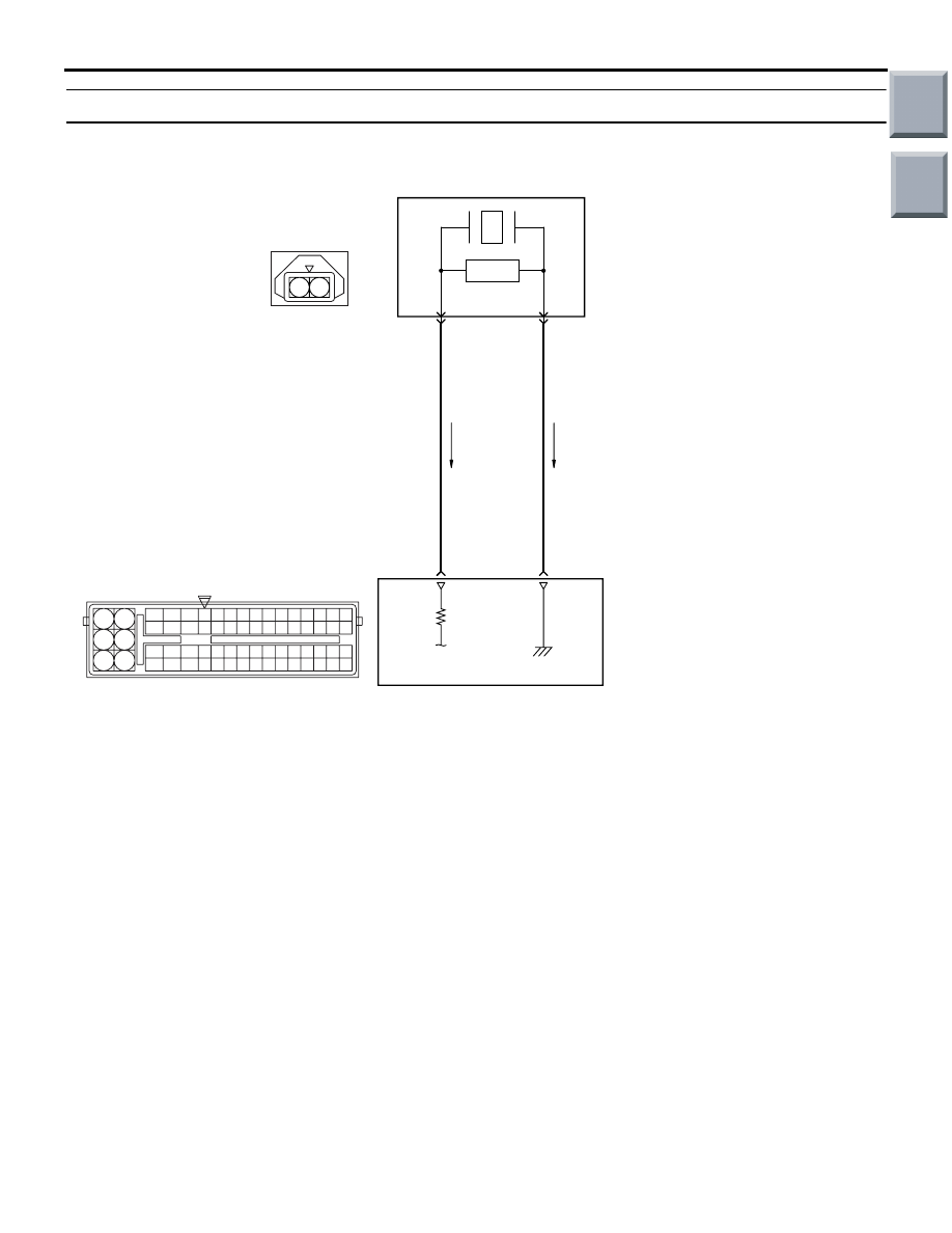
Code No. P0325: Detonation Sensor System
OPERATION
• The sensor signal is input to the engine-ECU (ter-
minal No. 20) from the detonation sensor (termi-
nal No. 2).
FUNCTION
• The detonation sensor detects vibration of the
cylinder block resulting from knocking and inputs
a signal to the engine-ECU.
• In response to the signal, the engine-ECU pro-
vides ignition-timing retarding control while
knocking condition persists.
TROUBLE JUDGEMENT
Check Conditions
• 2 seconds later from when engine starts
• Engine speed is more than 2,500 r/min.
• The volume efficiency is more than a prescribed
value.
Judgement Criterion
• When the amount of the change of continuous-
ness 200 times and the knock sensor output volt-
ages is minute.
PROBABLE CAUSES
• Failed detonation sensor
• Open/short circuit in or damage to detonation
sensor circuit, or loose connector contact
• Failed engine-ECU
AK402688
1 2
19
21
20
18
17
16
15
14
1213
11
8 9
L
10
37
52 53 54 555657585960616263646566
38 39 404142434445464748495051
22 23 24 252627282930313233343536
7
5
3
1
6
4
2
20
21
Detonation sensor
B
R
2
1
A-128
A-114
Detonation Sensor Circuit
AD
Wire colour code
B: Black LG: Light green G: Green L: Blue W: White Y: Yellow SB: Sky blue BR: Brown O: Orange GR: Gray
R: Red P: Pink V: Violet
P: Purple
Engine-ECU
Main
Index
Group
TOC
TROUBLESHOOTING
MULTIPORT FUEL INJECTION (MPI) <4G1>
13B-139
DIAGNOSIS PROCEDURE
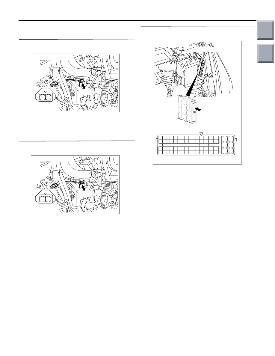
STEP 1. Connector check: A-128 detonation
sensor connector
Q: Is the check result normal?
YES :
Go to Step 2 .
NO :
Repair or replace.
STEP 2. Perform resistance measurement at
A-128 detonation sensor connector.
• Disconnect connector and measure at harness
side.
• Resistance between terminal No. 1 and earth.
OK: Continuity (2
Ω or less)
Q: Is the check result normal?
YES :
Go to Step 4 .
NO :
Go to Step 3 .
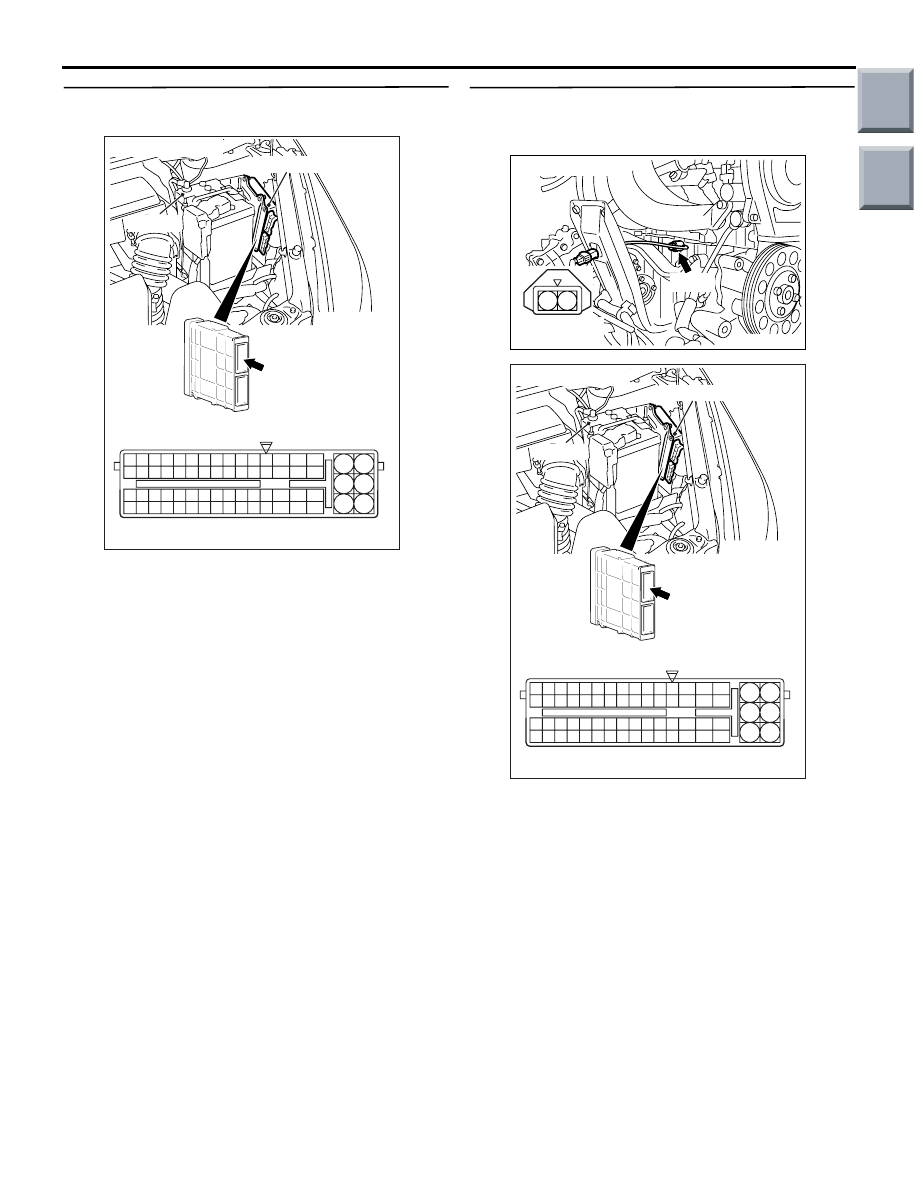
STEP 3. Connector check: A-114 engine-ECU
connector
Q: Is the check result normal?
YES :
Check and repair if necessary the harness
between A-128 (terminal No. 1) detonation
sensor connector and A-114 (terminal No.
21) engine-ECU connector.
NO :
Repair or replace.
AK402094
2 1
AD
Connector: A-128
Harness side
connector
A-128
AK402094
2 1
AD
Connector: A-128
Harness side
connector
A-128
AK402745
6
4
2
5
3
1
9
7
8
10
11
12
13
14
15
16
17
18
19
20
21
22
23
24
25
26
27
28
29
30
31
32
33
34
35
36
37
38
39
40
41
42
43
44
45
46
47
48
49
50
51
52
53
54
55
56
57
58
59
60
61
62
63
64
65
66
L
AF
A-114
Connector:
A-114
Harness side connector
Engine-ECU
Battery
Main
Index
Group
TOC
TROUBLESHOOTING
MULTIPORT FUEL INJECTION (MPI) <4G1>
13B-140
STEP 4. Connector check: A-114 engine-ECU
connector
Q: Is the check result normal?
YES :
Go to Step 5 .
NO :
Repair or replace.
STEP 5. Check harness between A-128 (terminal
No. 2) detonation sensor connector and A-114
(terminal No. 20) engine-ECU connector.
• Check output line for open/short circuit and dam-
age.
Q: Is the check result normal?
YES :
Go to Step 6 .
NO :
Repair.
AK402745
6
4
2
5
3
1
9
7
8
10
11
12
13
14
15
16
17
18
19
20
21
22
23
24
25
26
27
28
29
30
31
32
33
34
35
36
37
38
39
40
41
42
43
44
45
46
47
48
49
50
51
52
53
54
55
56
57
58
59
60
61
62
63
64
65
66
L
AF
A-114
Connector:
A-114
Harness side connector
Engine-ECU
Battery
AK402094
2 1
AD
Connector: A-128
Harness side
connector
A-128
AK402745
6
4
2
5
3
1
9
7
8
10
11
12
13
14
15
16
17
18
19
20
21
22
23
24
25
26
27
28
29
30
31
32
33
34
35
36
37
38
39
40
41
42
43
44
45
46
47
48
49
50
51
52
53
54
55
56
57
58
59
60
61
62
63
64
65
66
L
AF
A-114
Connector:
A-114
Harness side connector
Engine-ECU
Battery
Main
Index
Group
TOC
Нет комментариевНе стесняйтесь поделиться с нами вашим ценным мнением.
Текст