Mitsubishi Colt Ralliart. Manual — part 682
TROUBLESHOOTING
MULTIPORT FUEL INJECTION (MPI) <4G1>
13B-53
Code No. P0122: Throttle Position Sensor (Main) Circuit Low Input
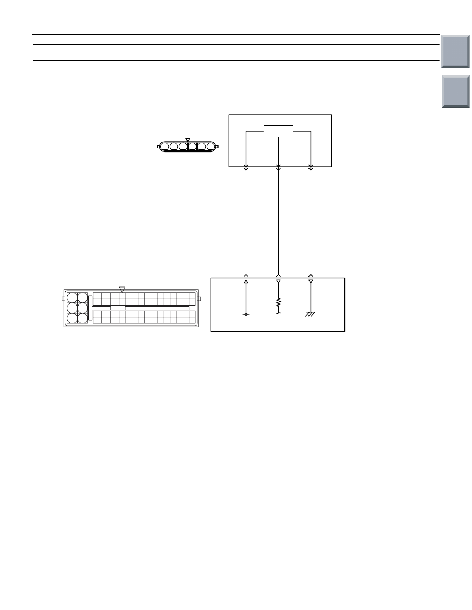
OPERATION
• A power voltage of 5 V is applied to the elec-
tronic-controlled throttle valve (terminal No. 2)
from the engine-ECU (terminal No. 31).
• The power voltage is earthed to the engine-ECU
(terminal No. 30) from the electronic-controlled
throttle valve (terminal No. 4).
• The sensor signal is inputted to the engine-ECU
(terminal No. 15) from the electronic-controlled
throttle valve output terminal (terminal No. 1).
FUNCTION
• The throttle position sensor converts the throttle
valve position into voltage and inputs it into the
engine-ECU.
• The engine-ECU controls the throttle valve posi-
tion.
TROUBLE JUDGMENT
Check Condition
• Ignition switch is in "ON" position.
Judgment Criterion
• Throttle position sensor (main) output voltage is
less than 0.2 V.
PROBABLE CAUSES
• Failed throttle position sensor (main)
• Open/short circuit and damage in throttle position
sensor circuit or loose connector contact
• Failed engine-ECU
AK402679
6
1 2 3 4 5
19
21
20
18
17
16
15
14
1213
11
8 9
L
10
37
52 53 54 555657585960616263646566
38 39 404142434445464748495051
22 23 24 252627282930313233343536
7
5
3
1
6
4
2
5 V
31
2
Electronic-controlled
throttle valve
B-W
R-W
Y-R
Engine-ECU
15
30
1
4
Throttle Position Sensor (main) Circuit
A-107
A-114
(main)
Hall IC
AF
Wire colour code
B: Black LG: Light green G: Green L: Blue W: White Y: Yellow SB: Sky blue BR: Brown O: Orange GR: Gray
R: Red P: Pink V: Violet P: Purple
Main
Index
Group
TOC

TROUBLESHOOTING
MULTIPORT FUEL INJECTION (MPI) <4G1>
13B-54
DIAGNOSIS PROCEDURE
STEP 1. M.U.T.-III data list
• Refer to Data List Reference Table
.
a. Item No. 79: Throttle position sensor (main)
Q: Is the check result normal?
YES :
Intermittent malfunction (Refer to GROUP
00
− How to Use Troubleshooting/Inspection
Service Points
− How to Cope with
Intermittent Malfunctions
).
NO :
Go to Step 2 .
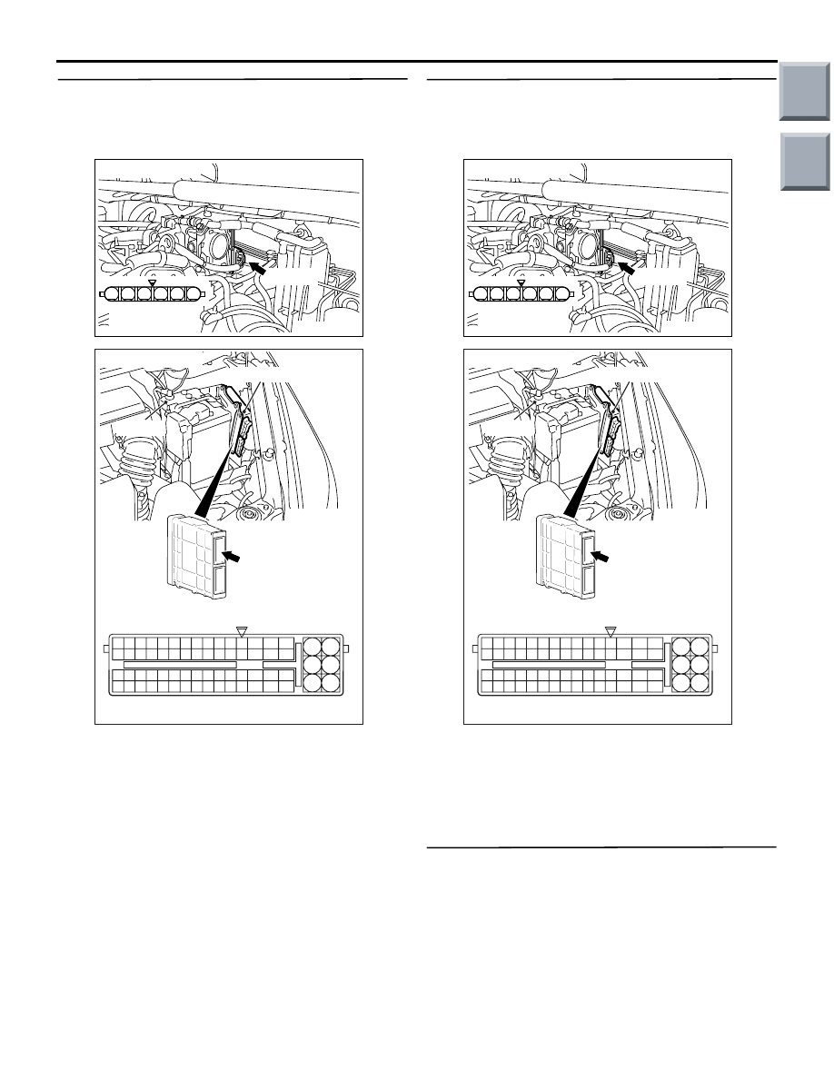
STEP 2. Connector check: A-107
electronic-controlled throttle valve connector
Q: Is the check result normal?
YES :
Go to Step 3 .
NO :
Repair or replace the connector.
STEP 3. Perform voltage measurement at A-107
electronic-controlled throttle valve connector.
• Disconnect connector, and measure at harness
side.
• Ignition switch: ON
• Voltage between terminal No. 2 and earth.
OK: 4.9
− 5.1 V
Q: Is the check result normal?
YES :
Go to Step 7 .
NO :
Go to Step 4 .
STEP 4. Connector check: A-114 engine-ECU
connector
Q: Is the check result normal?
YES :
Go to Step 5 .
NO :
Repair or replace the connector.
AK402086
1
6 5 4 3 2
A-107(B)
AC
Connector: A-107
Harness side
connector
AK402086
1
6 5 4 3 2
A-107(B)
AC
Connector: A-107
Harness side
connector
AK402745
6
4
2
5
3
1
9
7
8
10
11
12
13
14
15
16
17
18
19
20
21
22
23
24
25
26
27
28
29
30
31
32
33
34
35
36
37
38
39
40
41
42
43
44
45
46
47
48
49
50
51
52
53
54
55
56
57
58
59
60
61
62
63
64
65
66
L
AF
A-114
Connector:
A-114
Harness side connector
Engine-ECU
Battery
Main
Index
Group
TOC

TROUBLESHOOTING
MULTIPORT FUEL INJECTION (MPI) <4G1>
13B-55
STEP 5. Check harness between A-107 (terminal
No. 2) electronic-controlled throttle valve
connector and A-114 (terminal No. 31)
engine-ECU connector.
• Check power supply line for open/short circuit.
Q: Is the check result normal?
YES :
Go to Step 6 .
NO :
Repair the damaged harness wire.
STEP 6. M.U.T.-III data list
• Refer to Data List Reference Table
.
a. Item No. 79: Throttle position sensor (main)
Q: Is the check result normal?
YES :
Intermittent malfunction (Refer to GROUP
00
− How to Use Troubleshooting/Inspection
Service Points
− How to Cope with
Intermittent Malfunctions
).
NO :
Replace engine-ECU.
STEP 7. Connector check: A-114 engine-ECU
connector
Q: Is the check result normal?
YES :
Go to Step 8 .
NO :
Repair or replace the connector.
AK402086
1
6 5 4 3 2
A-107(B)
AC
Connector: A-107
Harness side
connector
AK402745
6
4
2
5
3
1
9
7
8
10
11
12
13
14
15
16
17
18
19
20
21
22
23
24
25
26
27
28
29
30
31
32
33
34
35
36
37
38
39
40
41
42
43
44
45
46
47
48
49
50
51
52
53
54
55
56
57
58
59
60
61
62
63
64
65
66
L
AF
A-114
Connector:
A-114
Harness side connector
Engine-ECU
Battery
AK402745
6
4
2
5
3
1
9
7
8
10
11
12
13
14
15
16
17
18
19
20
21
22
23
24
25
26
27
28
29
30
31
32
33
34
35
36
37
38
39
40
41
42
43
44
45
46
47
48
49
50
51
52
53
54
55
56
57
58
59
60
61
62
63
64
65
66
L
AF
A-114
Connector:
A-114
Harness side connector
Engine-ECU
Battery
Main
Index
Group
TOC
TROUBLESHOOTING
MULTIPORT FUEL INJECTION (MPI) <4G1>
13B-56
STEP 8. Check harness between A-107 (terminal
No. 2) electronic-controlled throttle valve
connector and A-114 (terminal No. 31)
engine-ECU connector.
• Check power supply line for damage.
Q: Is the check result normal?
YES :
Go to Step 9 .
NO :
Repair the damaged harness wire.
STEP 9. Check harness between A-107 (terminal
No. 1) electronic-controlled throttle valve
connector and A-114 (terminal No. 15)
engine-ECU connector.
• Check output line for open/short circuit and dam-
age.
Q: Is the check result normal?
YES :
Go to Step 10 .
NO :
Repair the damaged harness wire.
STEP 10. Replace the throttle body assembly
• After replacing the throttle body assembly
re-check the trouble symptoms.
Q: Is the check result normal?
YES :
Check end.
NO :
Replace engine-ECU.
AK402086
1
6 5 4 3 2
A-107(B)
AC
Connector: A-107
Harness side
connector
AK402745
6
4
2
5
3
1
9
7
8
10
11
12
13
14
15
16
17
18
19
20
21
22
23
24
25
26
27
28
29
30
31
32
33
34
35
36
37
38
39
40
41
42
43
44
45
46
47
48
49
50
51
52
53
54
55
56
57
58
59
60
61
62
63
64
65
66
L
AF
A-114
Connector:
A-114
Harness side connector
Engine-ECU
Battery
Main
Index
Group
TOC
Нет комментариевНе стесняйтесь поделиться с нами вашим ценным мнением.
Текст