Mitsubishi Colt Ralliart. Manual — part 430

INPUT SIGNAL PROCEDURES
SMART WIRING SYSTEM (SWS) USING SWS MONITOR
54C-228
Step 4. Check the wiring harness between D-08
front door lock actuator (RH) connector terminal
No.3 to body earth D-08
NOTE:
Prior to the wiring harness inspection, check interme-
diate connector B-21, and repair if necessary.
• Check the earth wires for open circuit.
Q: Is the check result normal?
YES :
The trouble can be an intermittent
malfunction (Refer to GROUP 00
− How to
use Troubleshooting/inspection Service
Points
− How to Cope with Intermittent
).
NO :
Repair the wiring harness.
Step 5. Connector check: B-132 ETACS-ECU
connector
Q: Is the check result normal?
YES :
Go to Step 6.
NO :
Repair the defective connector.
Step 6. Check the wiring harness from D-08 front
door lock actuator (RH) connector terminal No.1
and 2 to B-132 ETACS-ECU connector terminal
No.41 and 36.
NOTE:
Prior to the wiring harness inspection, check interme-
diate connector B-21, and repair if necessary.
• Check the input line for open circuit.
Q: Is the check result normal?
YES :
Go to Step 7.
NO :
Repair the wiring harness.
AC313837
Connector: D-08
D-08 (B)
AB
Harness side
AC401055
Connector: B-21
AB
AC313826 AD
Connector: B-132
Junction block (Rear view)
Harness side
AC313826 AD
Connector: B-132
Junction block (Rear view)
Harness side
AC313837
Connector: D-08
D-08 (B)
AB
Harness side
AC401055
Connector: B-21
AB
Main
Index
Group
TOC
INPUT SIGNAL PROCEDURES
SMART WIRING SYSTEM (SWS) USING SWS MONITOR
54C-229
Step 7. ETACS switch data by using the SWS
monitor
Check the input signal from the driver's door lock
actuator switch.
• Driver's door lock actuator switch: LOCK →
UNLOCK
OK: Normal conditions are displayed for all
the items.
Q: Are the check results normal?
YES :
The trouble can be an intermittent
malfunction (Refer to GROUP 00
− How to
use Troubleshooting/inspection Service
Points
− How to Cope with Intermittent
).
NO :
Replace the ETACS-ECU.
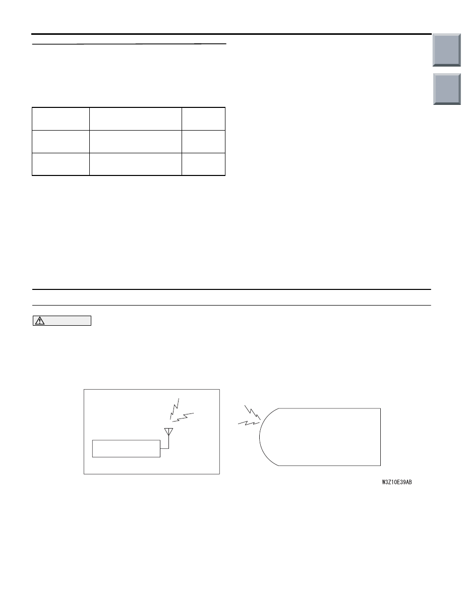
Inspection Procedure N-12: Each switch signal of the keyless entry transmitter is not received.
CAUTION
Whenever the ECU is replaced, ensure that the
input signal circuit is normal.
COMMENTS ON TROUBLE SYMPTOM
Input signal from the keyless entry transmitter is
used to operate the keyless entry system. If the sig-
nal is abnormal, the keyless entry system will not
work normally.
• Keyless entry system
• Keyless entry hazard answerback
• Multi-mode keyless entry system
POSSIBLE CAUSES
• Malfunction of the keyless entry transmitter
• Defective battery of the keyless entry transmitter
• Malfunction of the ETACS-ECU
Item No.
Item name
Normal
condition
Item 21
DR DOR LCK SW
from ON
to OFF
Item 22
DR DOR ULK SW
from OFF
to ON
KEYLESS ENTRY
TRANSMITTER
KEYLESS ENTRY
RECEIVER
ETACS-ECU
Transmitter Input Circuit
Main
Index
Group
TOC

INPUT SIGNAL PROCEDURES
SMART WIRING SYSTEM (SWS) USING SWS MONITOR
54C-230
DIAGNOSIS PROCEDURE
Step1. Use the SWS monitor to examine the
keyless entry system for signal reception.
• Use the defective keyless entry system transmit-
ter.
• Examine the signal reception from keyless entry
transmitter by operating the key switch. If signals
can be received from the transmitter, the monitor
screen shows signals relevant to each key
switch.
OK: Normal condition are displayed for all
items.
Q: Are the check result normal?
Normal condition are displayed for all items :
Go
to Step3.
Normal conditions are displayed for no items. :
Go
to Step2.
Normal condition is displayed for either of the
items. :
Replace the keyless entry transmitter.
Step 2. Register the encrypted code, and then
retest the system.
1. Register the keyless entry transmitter again.
2. Check that each signal is received from the key-
less entry transmitter.
Q: Is the check result normal?
YES :
Accidental erasure of the encrypted code Or
the key is mismatched. Check that the
customer is an authorised person.
NO :
Go to Step 3 (including the case that key
registration is not possible).
Step 3. Replace the battery of the keyless entry
transmitter, and retest the system.
1. Replace the battery of the keyless entry transmit-
ter.
2. Check that each signal is received from the key-
less entry transmitter.
Q: Is the check result normal?
YES :
Flat battery.
NO :
Go to Step4.
Step 4. Register the encrypted code again by
using a known good keyless entry transmitter.
Then retest the system.
1. Register a known good keyless entry transmitter
(the one which mounting screws are silver).
2. Check that each signal is received from the key-
less entry transmitter.
Q: Is the check result normal?
YES :
Replace the original keyless entry
transmitter.
NO :
Replace the ETACS-ECU (including the
case where registration is impossible).
Key switch operation
Display on
M.U.T.-III
LOCK switch
LOCK
UNLOCK switch
UNLOCK
Press and hold the LOCK switch
for at least one second
LCK LNG PUSH
Press and hold the UNLOCK
switch for at least one second
ULCK LNG
PUSH
Main
Index
Group
TOC
INPUT SIGNAL PROCEDURES
SMART WIRING SYSTEM (SWS) USING SWS MONITOR
54C-231
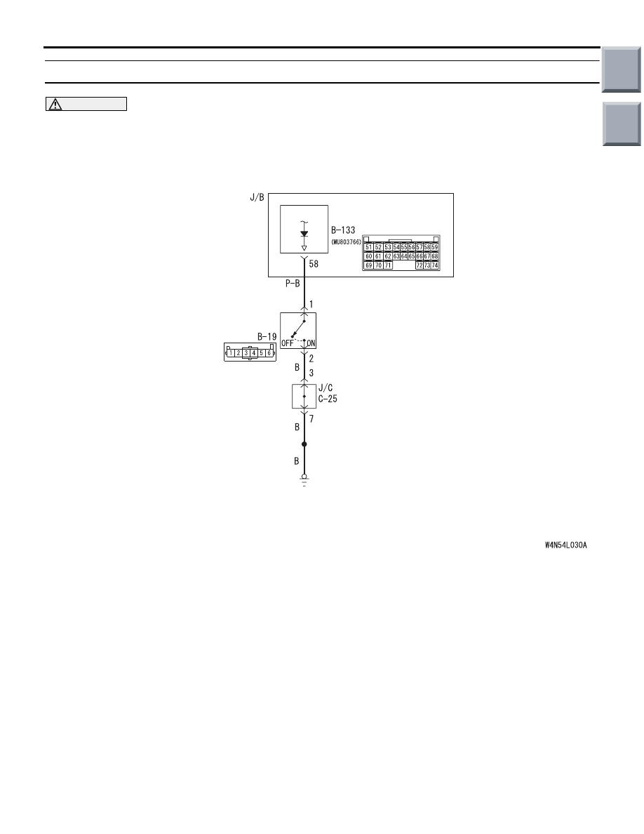
Inspection Procedure N-13: The fog lamp switch signal is not received.
CAUTION
Whenever the ECU is replaced, ensure that the
input signal circuit is normal.
COMMENTS ON TROUBLE SYMPTOM
Input signal from the fog lamp switch is used to oper-
ate the fog lamps. If the signal is abnormal, the fog
lamps will not illuminate and extinguish normally.
POSSIBLE CAUSES
• Malfunction of the fog lamp switch
• Malfunction of the ETACS-ECU
• Damaged harness wires and connectors
ETACS-
ECU
FOG LAMP
SWITCH
Fog Lamp Switch Input Circuit
Wire colour code
B : Black LG : Light green G : Green L : Blue W : White Y : Yellow SB : Sky blue
BR : Brown O : Orange GR : Gray R : Red P : Pink V : Violet
Main
Index
Group
TOC
Нет комментариевНе стесняйтесь поделиться с нами вашим ценным мнением.
Текст