Mitsubishi Colt Ralliart. Manual — part 12
GENERAL INFORMATION
MULTIPORT FUEL INJECTION (MPI) <4A9>
13A-2
GENERAL INFORMATION
M1131000102741
The Multipoint Fuel Injection System consists of sen-
sors which detect the engine conditions, the
engine-ECU <M/T> or engine-CVT-ECU <CVT>
which controls the system based on signals from
these sensors, and actuators which operate under
the control of the engine-ECU <M/T> or
engine-CVT-ECU <CVT>. The engine-ECU <M/T>
or engine-CVT-ECU <CVT> carries out activities
such as fuel injection control, idle speed control and
ignition timing control. In addition, the engine-ECU
<M/T> or engine-CVT-ECU <CVT> is equipped with
several diagnosis modes which simplify trouble-
shooting when a problem develops.
FUEL INJECTION CONTROL
The injector drive times and injection timing are con-
trolled so that the optimum air/fuel mixture is sup-
plied to the engine to correspond to the
continually-changing engine operation conditions.
A single injector is mounted at the intake port of each
cylinder. Fuel is sent under pressure from the fuel
tank by the fuel pump, with the pressure being regu-
lated by the fuel pressure regulator. The fuel thus
regulated is distributed to each of the injectors.
Fuel injection is normally carried out once for each
cylinder for every two rotations of the crankshaft. The
firing order is 1-3-4-2. This is called sequential fuel
injection. The engine-ECU <M/T> or
engine-CVT-ECU <CVT> provides a richer air/fuel
mixture by carrying out "open-loop" control when the
engine is cold or operating under high load condi-
tions in order to maintain engine performance. In
addition, when the engine is warm or operating under
normal conditions, the engine-ECU <M/T> or
engine-CVT-ECU <CVT> controls the air/fuel mixture
by using the oxygen sensor signal to carry out
"closed-loop" control in order to obtain the theoretical
air/fuel mixture ratio that provides the maximum
cleaning performance from the three way catalyst.
THROTTLE VALVE OPENING CONTROL
This system electrically controls the opening of the
throttle valve. The engine-ECU <M/T> or
engine-CVT-ECU <CVT> detects the amount of
travel of the accelerator pedal via the accelerator
pedal position sensor, and controls the actuation of
the throttle valve control servo, which is mounted on
the throttle body, in order to attain the target throttle
valve opening that has been predetermined in
accordance with driving conditions.
IDLE SPEED CONTROL
The idle speed is kept at the optimum speed by con-
trolling the amount of air that passes through the
throttle valve in accordance with changes in idling
conditions and engine load during idling.
The engine-ECU <M/T> or engine-CVT-ECU <CVT>
drives the throttle valve control servo to keep the
engine running at the pre-set idle target speed in
accordance with the engine coolant temperature and
A/C and other electrical load. In addition, when the
air conditioning switch is turned off and on while the
engine is idling, the throttle valve control servo
adjusts the throttle valve passes through air amount
according to the engine load conditions to avoid fluc-
tuations in the engine speed.
IGNITION TIMING CONTROL
The power transistor located in the ignition primary
circuit turns ON and OFF to control the primary cur-
rent flow to the ignition coil. This controls the ignition
timing in order to provide the optimum ignition timing
with respect to the engine operating conditions. The
ignition timing is determined by the engine-ECU
<M/T> or engine-CVT-ECU <CVT> from the engine
speed, intake air volume, engine coolant tempera-
ture and atmospheric pressure.
Main
Index
Group
TOC
GENERAL INFORMATION
MULTIPORT FUEL INJECTION (MPI) <4A9>
13A-3
SELF-DIAGNOSIS FUNCTION
• When an abnormality is detected in one of the
sensors or actuators related to emission control,
the engine warning lamp (check engine lamp)
illuminates as a warning to the driver.
• When an abnormality is detected in one of the
sensors or actuators, a diagnosis code corre-
sponding to the abnormality is output.
• The RAM data inside the engine-ECU <M/T> or
engine-CVT-ECU <CVT> that is related to the
sensors and actuators can be read by means of
the M.U.T.-III. In addition, the actuators can be
force-driven under certain circumstances.
OTHER CONTROL FUNCTIONS
1. Fuel Pump Control
Turns the fuel pump relay ON so that current is sup-
plied to the fuel pump while the engine is crank-
ing or running.
2. A/C Relay Control
Turns the compressor clutch of the A/C ON and OFF.
3. Oil Feeder Control Valve Control
The engine-ECU <M/T> or engine-CVT-ECU <CVT>
carries out the duty control of the oil feeder con-
trol valve according to the operation condition.
This varies the phase angle of the intake cam-
shaft to optimize the intake valve timing.
4. Fan Motor Control
The revolutions of the cooling fan is controlled in
response to the engine coolant temperature and
vehicle speed.
5. Alternator Output Current Control
Prevents alternator output current from increasing
suddenly and idle speed from dropping at times
such as when the headlamp are turned on.
6. Purge Control Solenoid Valve Control
(Refer to
, GROUP 17
− Engine And Emis-
sion Control
− Evaporative Emission Control Sys-
tem).
7. EGR Control Solenoid Valve Control <CVT>
[Refer to
, GROUP 17
− Engine And Emis-
sion Control
− Exhaust Gas Recirculation (EGR)
System].
Main
Index
Group
TOC
GENERAL INFORMATION
MULTIPORT FUEL INJECTION (MPI) <4A9>
13A-4
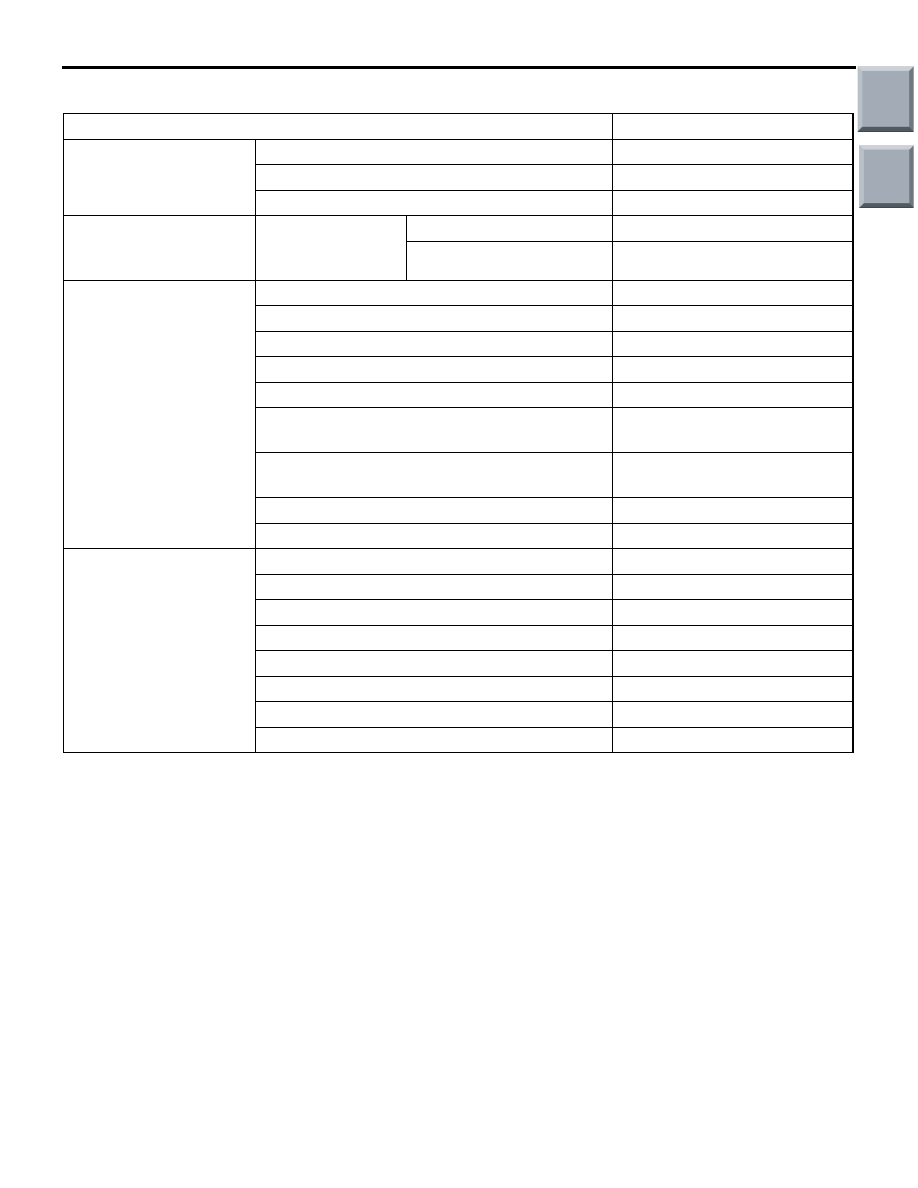
GENERAL SPECIFICATIONS
Items
Specifications
Throttle body
Throttle bore mm
45
Throttle position sensor
Hall element type
Throttle valve control servo
DC motor type, having broshes
Engine-ECU <M/T> or
engine-CVT-ECU
<CVT>
Identification No.
Engine-ECU <M/T>
E6T45193
Engine-CVT-ECU <CVT>
E6T45186
Sensors
Barometric pressure sensor
Semiconductor type
Intake air temperature sensor
Thermistor type
Engine coolant temperature sensor
Thermistor type
Oxygen sensor
Zirconia type
Accelerator pedal position sensor
Hall element type
Camshaft position sensor
Magneto resistance element
type
Crank angle sensor
Magneto resistance element
type
Detonation sensor
Piezoelectric type
Manifold absolute pressure sensor
Semiconductor type
Actuators
Engine control relay type
Contact switch type
Fuel pump relay type
Contact switch type
Injector type and number
Electromagnetic type, 4
Injector identification mark
CDH166
Throttle valve control servo relay
Contact switch type
Oil feeder control valve
Duty cycle type solenoid valve
EGR valve <CVT>
Stepper motor
Purge control solenoid valve
Duty cycle type solenoid valve
Main
Index
Group
TOC
GENERAL INFORMATION
MULTIPORT FUEL INJECTION (MPI) <4A9>
13A-5
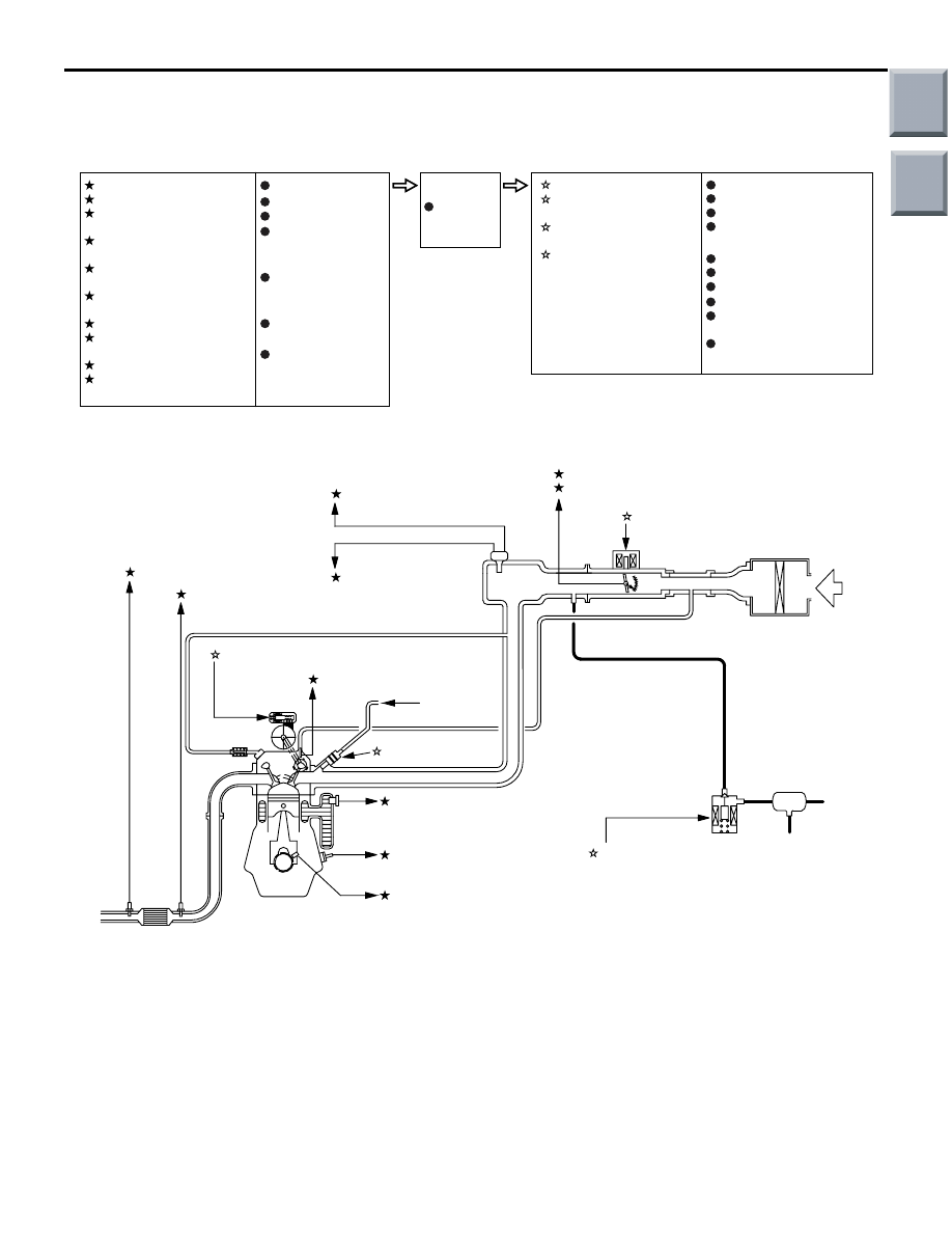
MULTI-POINT FUEL INJECTION SYSTEM DIAGRAM
<M/T>
AK600525
1 Oxygen sensor
(front)
4 Intake air temperature
sensor
3 Manifold absolute
presssure sensor
2 Oxygen sensor (rear)
3 Throttle valve control
servo
10 Throttle position sensor
(main)
2 Purge control
solenoid valve
8 Engine coolant
temperature sensor
9 Detonation sensor
7 Crank angle sensor
6 Camshaft position sensor
4 Oil feeder control valve
1 Injector
AB
M
1 Oxygen sensor (front)
2 Oxygen sensor (rear)
3 Manifold absolute
presssure sensor
4 Intake air temperature
sensor
5 Throttle position
sensor
(sub)
6 Camshaft position
sensor
7 Crank angle sensor
8 Engine coolant
temperature sensor
9 Detonation sensor
10 Throttle position
sensor
(main)
1 Injector
2 Purge control
solenoid valve
3 Throttle valve control
servo
4 Oil feeder control
valve
Power supply
Ignition switch-IG
Ignition switch-ST
Accelerator pedal
position sensor
(main)
Accelerator pedal
position sensor
(sub)
Alternator FR
terminal
Stop lamp switch
Engine-ECU
Engine control relay
Fuel pump relay
A/C compressor relay
Throttle valve
control servo relay
Ignition coil
Cooling fan
control
relay
Diagnosis output
Alternator G terminal
Oxygen sensor heater
(front)
Oxygen sensor heater
(rear)
Canister
Air
inlet
Catalytic converter
From fuel
pump
5 Throttle position sensor
(sub)
Barometric
pressure
sensor
Main
Index
Group
TOC
Нет комментариевНе стесняйтесь поделиться с нами вашим ценным мнением.
Текст