Mitsubishi Colt Ralliart. Manual — part 27

TROUBLESHOOTING
MULTIPORT FUEL INJECTION (MPI) <4A9>
13A-62
Code No. P0130: Oxygen Sensor (Front) System
OPERATION
• The sensor signal is inputted to the engine-ECU
<M/T> or engine-CVT-ECU <CVT> (terminal No.
34) from the oxygen sensor output terminal (ter-
minal No. 1).
• The oxygen sensor (front) (terminal No. 2) is
earthed with engine-ECU <M/T> or
engine-CVT-ECU <CVT> (terminal No. 49).
FUNCTION
• The oxygen sensor converts the concentration of
oxygen in the exhaust emission into a voltage
and inputs the signal to the engine-ECU <M/T> or
engine-CVT-ECU <CVT>.
• When the air-fuel ratio is richer than the theoreti-
cal air-fuel ratio, the oxygen sensor outputs a
voltage of about 1 V. When it is leaner than the
theoretical air-fuel ratio, it outputs a voltage of
about 0 V.
• In response to the signal, the engine-ECU <M/T>
or engine-CVT-ECU <CVT> controls the fuel
infection amount so that the air-fuel ratio can be
equivalent to the theoretical air-fuel ratio.
TROUBLE JUDGMENT
Check Conditions
• Above 5 minutes later after the engine has
started up.
• The engine coolant temperature is above 82°C
for 5 seconds or longer <M/T>.
• The engine speed is above 1,200 r/min for 5 sec-
onds or longer <M/T>.
AK503587
1 2
4
3
19
21
20
18
17
16
15
14
1213
11
8 9
L
10
37
52 53 54 555657585960616263646566
38 39 404142434445464748495051
22 23 24 252627282930313233343536
7
5
3
1
6
4
2
Oxygen sensor (front)
Y
GR
From engine control relay
3
2
4
1
49
34
A-122
MU802083
A-114
Engine-ECU <M/T> or
engine-CVT-ECU <CVT>
To engine-ECU <M/T> or
engine-CVT-ECU <CVT>
AC
Wire colour code
B: Black LG: Light green G: Green L: Blue W: White Y: Yellow SB: Sky blue BR: Brown O: Orange GR: Gray
R: Red P: Pink V: Violet PU: Purple
Oxygen Sensor Circuit (front)
Main
Index
Group
TOC
TROUBLESHOOTING
MULTIPORT FUEL INJECTION (MPI) <4A9>
13A-63
• The intake manifold pressure is above 20 kPa for
5 seconds or longer <M/T>.
• Oxygen sensor (front) output voltage is 0.5 V or
less <CVT>.
• The engine coolant temperature is approximately
80
°C or higher <CVT>.
• The engine speed is 1,200 r/min or more <CVT>.
• During the run at the constant speed on the flat
road <CVT>.
Judgment Criteria
• When 5 V is applied to oxygen sensor (front) out-
put line via register, engine-ECU-interface output
voltage is more than 4.0 V <M/T>.
• When a power voltage of 5 V is applied to the
oxygen sensor, the sensor output voltage is 4.0 V
or more <CVT>.
Check Conditions
• Engine speed is more than 1,200 r/min and is
less than 3,000 r/min <M/T>.
• The engine coolant temperature is above 50°C
<M/T>.
• The intake manifold pressure is more than 30
kPa and is less than 60 kPa <M/T>.
• Within the range of air-fuel ratio feedback opera-
tion <M/T>.
Judgment Criterion
• The oxygen sensor (front) sends "lean" and "rich"
signals alternately 6 times or less for 10 seconds
<M/T>.
PROBABLE CAUSES
• Failed oxygen sensor
• Open/short circuit in oxygen sensor circuit or
loose connector contact
• Failed engine-ECU <M/T> or engine-CVT-ECU
<CVT>
DIAGNOSIS PROCEDURE
STEP 1. M.U.T.-III data list
• Refer to Data List Reference Table
.
a. Item 11: Oxygen sensor (front)
Q: Is the check result normal?
YES :
Intermittent malfunction (Refer to GROUP
00
− How to Use
Troubleshooting/Inspection Service Points
−
How to Cope with Intermittent Malfunctions
).
NO :
Go to Step 2 .
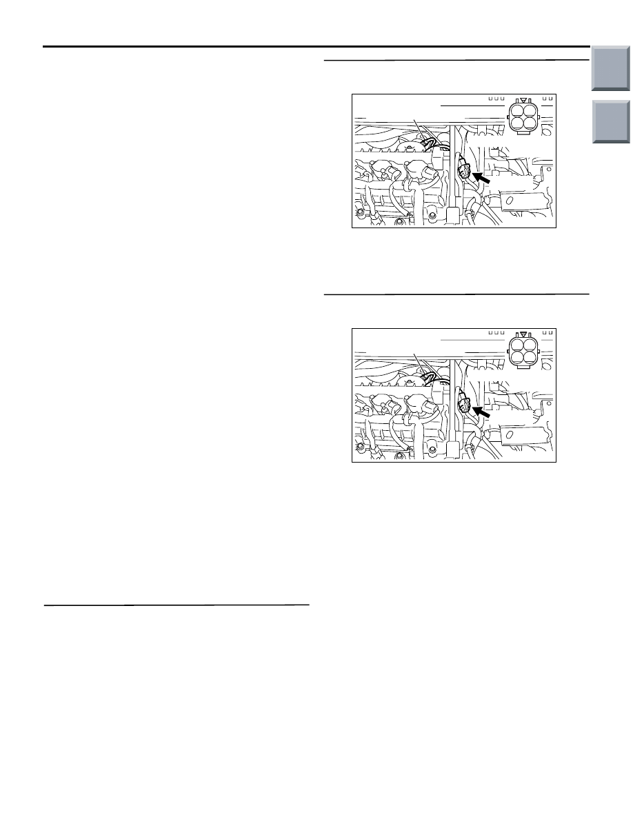
STEP 2. Connector check: A-122 oxygen sensor
(front) connector
Q: Is the check result normal?
YES :
Go to Step 3 .
NO :
Repair or replace the connector.
STEP 3. Perform resistance measurement at
A-122 oxygen sensor (front) connector.
• Disconnect connector, and measure at harness
side.
• Resistance between terminal No. 2 and earth.
OK: Continuity (2
Ω or less)
Q: Is the check result normal?
YES :
Go to Step 7 .
NO :
Go to Step 4 .
AK402012
2 1
4 3
Connector: A-122
A-122 (G)
AC
Oxygen sensor (front)
A-122 Harness side
connector
AK402012
2 1
4 3
Connector: A-122
A-122 (G)
AC
Oxygen sensor (front)
A-122 Harness side
connector
Main
Index
Group
TOC

TROUBLESHOOTING
MULTIPORT FUEL INJECTION (MPI) <4A9>
13A-64
STEP 4. Connector check: A-114 engine-ECU
connector or engine-CVT-ECU connector
Q: Is the check result normal?
YES :
Go to Step 5 .
NO :
Repair or replace the connector.
STEP 5. Check harness between A-122 (terminal
No. 2) oxygen sensor connector and A-114
(terminal No. 49) engine-ECU connector or
engine-CVT-ECU connector.
• Check earthing line for open circuit and damage.
Q: Is the check result normal?
YES :
Go to Step 6 .
NO :
Repair the damaged harness wire.
STEP 6. M.U.T.-III data list
• Refer to Data List Reference Table
.
a. Item 11: Oxygen sensor (front)
Q: Is the check result normal?
YES :
Intermittent malfunction (Refer to GROUP
00
− How to Use Troubleshooting/Inspection
Service Points
− How to Cope with
Intermittent Malfunctions
).
NO :
Replace engine-ECU <M/T> or
engine-CVT-ECU <CVT>.
AK402745
6
4
2
5
3
1
9
7
8
10
11
12
13
14
15
16
17
18
19
20
21
22
23
24
25
26
27
28
29
30
31
32
33
34
35
36
37
38
39
40
41
42
43
44
45
46
47
48
49
50
51
52
53
54
55
56
57
58
59
60
61
62
63
64
65
66
L
AD
A-114
Connector:
A-114
Harness side connector
Engine-ECU <M/T> or
engine-CVT-ECU <CVT>
Battery
AK402012
2 1
4 3
Connector: A-122
A-122 (G)
AC
Oxygen sensor (front)
A-122 Harness side
connector
AK402745
6
4
2
5
3
1
9
7
8
10
11
12
13
14
15
16
17
18
19
20
21
22
23
24
25
26
27
28
29
30
31
32
33
34
35
36
37
38
39
40
41
42
43
44
45
46
47
48
49
50
51
52
53
54
55
56
57
58
59
60
61
62
63
64
65
66
L
AD
A-114
Connector:
A-114
Harness side connector
Engine-ECU <M/T> or
engine-CVT-ECU <CVT>
Battery
Main
Index
Group
TOC

TROUBLESHOOTING
MULTIPORT FUEL INJECTION (MPI) <4A9>
13A-65
STEP 7. Perform voltage measurement at A-122
oxygen sensor connector.
• Use special tool test harness (MD991658) to con-
nect connector, and measure at pick-up harness.
• Engine: After warm-up
• Transmission: P range
• Voltage between terminal No. 2 and earth.
OK: 0.5 V or less
Q: Is the check result normal?
YES :
Go to Step 9 .
NO :
Go to Step 8 .
STEP 8. Connector check: A-114 engine-ECU
connector or engine-CVT-ECU connector
Q: Is the check result normal?
YES :
Check and repair harness between A-122
(terminal No. 2) oxygen sensor connector
and A-114 (terminal No. 49) engine-ECU
connector or engine-CVT-ECU connector.
• Check output line for damage.
NO :
Repair or replace the connector.
AK402012
2 1
4 3
Connector: A-122
A-122 (G)
AC
Oxygen sensor (front)
A-122 Harness side
connector
AK402745
6
4
2
5
3
1
9
7
8
10
11
12
13
14
15
16
17
18
19
20
21
22
23
24
25
26
27
28
29
30
31
32
33
34
35
36
37
38
39
40
41
42
43
44
45
46
47
48
49
50
51
52
53
54
55
56
57
58
59
60
61
62
63
64
65
66
L
AD
A-114
Connector:
A-114
Harness side connector
Engine-ECU <M/T> or
engine-CVT-ECU <CVT>
Battery
AK402012
2 1
4 3
Connector: A-122
A-122 (G)
AC
Oxygen sensor (front)
A-122 Harness side
connector
Main
Index
Group
TOC
Нет комментариевНе стесняйтесь поделиться с нами вашим ценным мнением.
Текст