Mitsubishi Colt Ralliart. Manual — part 455

ON-VEHICLE SERVICE
POWER STEERING
37-87
ON-VEHICLE SERVICE
STEERING WHEEL FREE PLAY CHECK
M1372001000582
1. With the engine running, set the front wheels
straight ahead.
AC000987
2. Measure the play on the steering wheel
circumference before the tyre & wheel start to
move when slightly moving the steering wheel in
both directions.
Limit: 30 mm
3. When the play exceeds the limit, check for the
play on the steering shaft and steering linkage
connection. Correct or replace.
4. If the play still exceeds the specification after
inspecting item 3, inspect the steering gear &
linkage assembly, and replace as necessary
(Refer to
STEERING ANGLE CHECK
M1372001100857
1. Adjust toe-in (Refer to GROUP 33, On-vehicle
Service
− Front Wheel Alignment Check and
AC000756AB
2. Place the front wheel on a turning radius gauge
and measure the steering angle.
Standard value:
Inner wheels
Vehicles with
14-inch wheels
41
° 40' ± 1° 30'
Vehicles with
15-inch wheels
39
° 00' ± 1° 30'
Vehicles with
16-inch wheels
34
° 10' ± 1° 30'
Outer wheels
(reference)
Vehicles with
14-inch wheels
35
° 30'
Vehicles with
15-inch wheels
33
° 40'
Vehicles with
16-inch wheels
30
° 00'
3. If not within the specification, replace the steering
gear and linkage assembly (Refer to
).
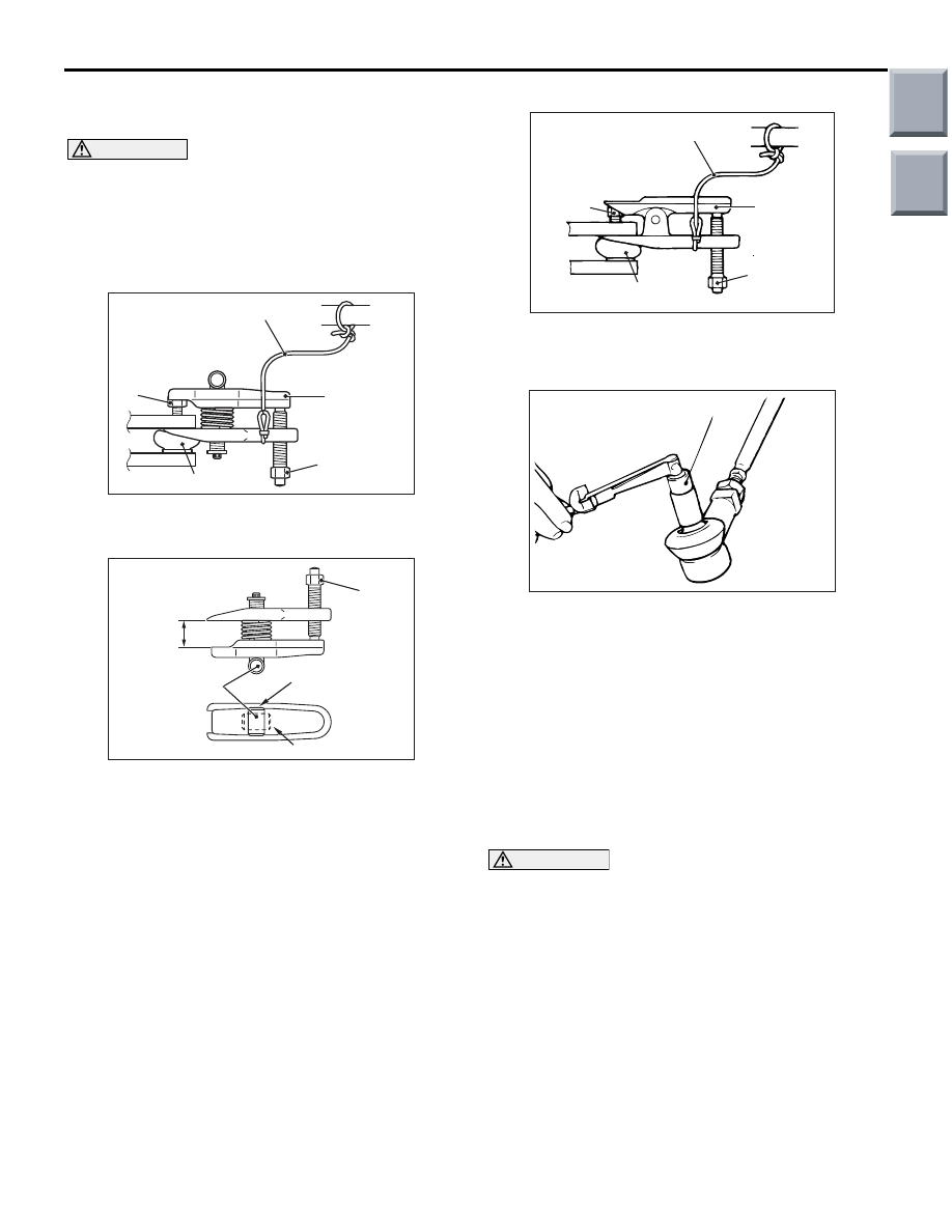
TIE ROD END BALL JOINT TURNING
TORQUE CHECK
M1372001500651
BALL JOINT LOOSENESS CHECK
1. Raise the vehicle.
2. Inspect the ball joint for looseness in the axial
direction while shaking the tie-rod end vertically. If
there is looseness, replace the tie-rod end
assembly.
Main
Index
Group
TOC
ON-VEHICLE SERVICE
POWER STEERING
37-88
BALL JOINT ROTATIONAL STARTING
TORQUE CHECK
CAUTION
• Do not remove the nut from ball joint. Loosen
it and use the special tool to avoid possible
damage to ball joint threads.
• Hang the special tool with cord to prevent it
from falling.
<4A9>
AC208247AJ
Cord
Bolt
MB991897
or
MB992011
Nut
Ball joint
1. Install special tool ball joint remover (MB991897
or MB992011) as shown in the figure.
AC106821
Knob
Parallel
Bolt
Correct
Wrong
AD
2. Turn the bolt and knob as necessary to make the
jaws of special tool parallel, tighten the bolt by
hand and confirm that the jaws are still parallel.
NOTE: When adjusting the jaws in parallel, make
sure the knob is in the position shown in the fig-
ure.
3. Tighten the bolt with a wrench to disconnect the
tie rod end, lower arm ball joint.
<4G1>
AC102599AC
Cord
Bolt
MB991113
Nut
Ball joint
Replace the self-locking nut with a regular nut, and
then install special tool steering linkage puller
(MB991113) as shown in the figure.
ACX01129 AB
MB990326
4. Move the ball joint stud several times and install
the nut on the stud. Using special tool preload
socket (MB990326), measure the ball joint turning
torque.
Standard value: 10 N
⋅m or less
5. If the turning torque exceeds the standard value,
replace the tie rod end.
6. If the turning torque is under the standard value,
check the ball joint for axial play or ratcheting. If
no axial play or ratcheting, the ball joint can be
re-used.
CAUTION
Always use a new ball joint nut as it is a self-lock-
ing nut.
7. Install the tie rod end to the knuckle, then tighten a
new self-locking nut to the specified torque.
Tightening torque: 25
± 5 N⋅m <4A9>
Tightening torque: 28
± 3 N⋅m <4G1>
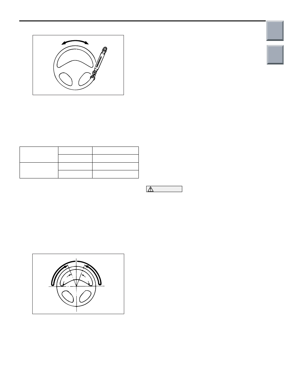
CHECK OF STEERING FORCE TO LOCK
M1372001700688
1. Verify that the tyre pressure is within the
specification. Use tyres with more than 80% of the
tread depth remained.
Specified tyre inflation pressure: 220 kPa
2. Place the vehicle on a level surface and turn the
steering wheel to the straight ahead position.
Main
Index
Group
TOC
ON-VEHICLE SERVICE
POWER STEERING
37-89
3. Start the engine.
AC000987
4. Attach a spring scale to the circumference of the
steering wheel and measure the steering force
when the steering wheel is turned to left and right
from the straight ahead position within 90
°. At the
same time, verify that the steering force does not
vary excessively in both directions.
Standard value:
Steering force
4A9
25 N or less
4G1
40 N or less
Fluctuation
4A9
6.0 N or less
4G1
10.0 N or less
5. If not within the specification, inspect and adjust
the steering system components.
STEERING WHEEL RETURN TO CENTRE
CHECK
M1372001800436
Carry out the test run for return check and check the
following.
1. Carry out gentle cornering and hard cornering and
check the steering force and the return do not
have the difference between left and right by the
feeling.
AC000989
70˚
AD
70˚
2. Turn the steering wheel at a 90
° angle and keep it
for a few seconds while driving at about 35 km/h
speed and then check that the steering wheel
returns more than 70
° when taking hand off.
TIE ROD END BALL JOINT DUST COVER
CHECK
M1372008600381
1. Press the dust cover with your finger to check
whether the dust cover is cracked or damaged.
2. If the dust cover is cracked or damaged, replace
the tie rod end.
NOTE: If the dust cover is cracked or damaged,
the ball joint could be damaged.
STEERING COLUMN SHAFT ASSEMBLY
SHOCK ABSORBING MECHANISM
CHECK
M1372013500368
If a collision accident occurs or severe impact is
applied on the steering wheel, the collision energy
absorbing mechanism may have operated. Once the
mechanism has operated, it will be inoperative even
it has suffered no apparent damage. Determine if the
steering column shaft can be reused by the following
procedure. If the collision energy absorbing mecha-
nism has already operated, replace the steering col-
umn shaft assembly.
If any excessive radial free play on the steering
wheel is found with the tilt lever in the lock position,
always check the steering shaft assembly.
WARNING
If the vehicle continues to be driven after the
collision absorbing mechanism has oper-
ated, the steering column shaft may be dam-
aged while it is in use.
Main
Index
Group
TOC

STEERING WHEEL
POWER STEERING
37-90
STEERING WHEEL
REMOVAL AND INSTALLATION
M1372011400365
WARNING
•
Before removing the steering wheel and air bag module assembly, refer to GROUP 52B,
Service Precautions (
) and Driver’s, Front Passenger’s Air Bag Module(s) and
).
•
Post-installation Operation
• Checking Steering Wheel Position with Wheels Straight
Ahead
• Steering wheel free play check (Refer to
AC207738
AC207739
AC207731
AC208946
AB
41 ± 8 N·m
1
2
3
N
2
3
1
2
3
9.0 ± 2.0 N·m
Claw
Claw
Removal steps
<<
A
>>
>>
A
<<
1.
Steering wheel lower cover
•
Horn connector connection
<<
B
>>
•
Air bag module connector
connection
<<
C
>>
2.
Air bag module
<<
D
>>
3.
Steering wheel assembly
When removing and installing the steering wheel, do not let it bump against the air bag
module.
Removal steps (Continued)
Main
Index
Group
TOC
Нет комментариевНе стесняйтесь поделиться с нами вашим ценным мнением.
Текст