Mitsubishi Colt Ralliart. Manual — part 550
TROUBLESHOOTING
SUPPLEMENTAL RESTRAINT SYSTEM (SRS)
52B-38
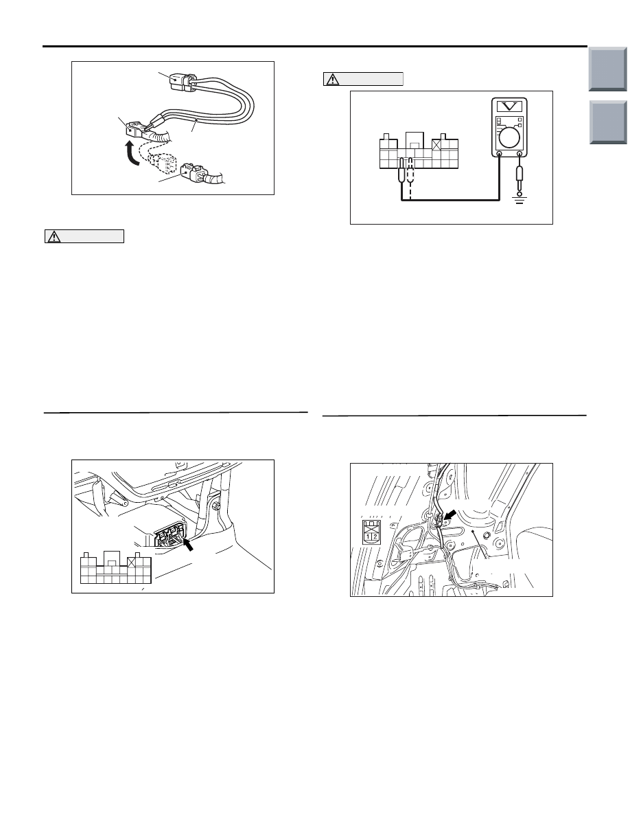
(3) Connect special tool dummy resistor (MB991865)
to special tool resistor harness (MB991866).
CAUTION
Do not insert a test probe into the terminal from
its front side directly as the connector contact
pressure may be weakened.
(4) Connect special tool (MB991866) to the C-13
harness side connector by backprobing.
(5) Connect the negative battery terminal.
(6) Erase diagnosis code memory, and check the
diagnosis code.
Q: Is diagnosis code 4E set?
YES :
Go to Step 2.
NO :
Go to Step 3.
STEP 2. Voltage measurement at the SRS-ECU
connector B-34.
(1) Disconnect the negative battery terminal.
(2) Disconnect SRS-ECU connector B-34.
(3) Connect the negative battery terminal.
(4) Turn the ignition switch to the "ON" position.
CAUTION
Do not insert a test probe into the terminal from
its front side directly as the connector contact
pressure may be weakened.
(5) Voltage measurement between B-34 harness
side connector terminals 27, 28 and body earth.
OK: 0 V
Q: Is the check results normal?
YES :
Go to Step 4.
NO :
Repair the harness wire between SRS-ECU
connector B-34 (terminal No.27 and 28) and
curtain air bag module (LH) side connector
C-13 (terminal No.2 and 1).
STEP 3. Voltage measurement at the curtain air
bag harness connector C-13.
(1) Disconnect the negative battery terminal.
(2) Disconnect intermediate connector C-13
(connection between curtain air bag harness and
floor harness).
(3) Connect the negative battery terminal.
(4) Turn the ignition switch to the "ON" position.
AC006042 CK
MB991866
(Resistor harness)
C-13
Intermediate h
arness side
connector
MB991865 (Dummy
resistor: 3
Ω)
C-13 Curtain air bag
module (LH) side connector
AC206285
AG
B-34 (Y)
Connector: B-34
Harness side
connector
(rear view)
343536373839404142
252627282930313233
2122
2324
AC100341
34 35 36 37 38 39 40 41 42
25 26 27 28 29 30 31 32 33
21 22
23 24
B-34 Harness side
connector (rear view)
AU
AC209027
Connector: C-13
C-13 (R)
Quarter panel
AC
Harness side
Main
Index
Group
TOC
TROUBLESHOOTING
SUPPLEMENTAL RESTRAINT SYSTEM (SRS)
52B-39
CAUTION
Do not insert a test probe into the terminal from
its front side directly as the connector contact
pressure may be weakened.
(5) Voltage measurement between C-13 curtain air
bag module (LH) side connector terminals 1, 2
and body earth.
OK: 0 V
Q: Is the check results normal?
YES :
Replace the curtain air bag module (Refer
to
NO :
Repair the harness wire between curtain air
bag module (LH) connector C-13 (terminal
No.1 and 2) and curtain air bag module
connector C-10 (terminal No.1and 2).
STEP 4. Check whether the diagnosis code is
reset.
Q: Is diagnosis code 4E set?
YES :
Replace the SRS-ECU (Refer to
).
NO :
An intermittent malfunction is suspected
(Refer to GROUP 00, How to Cope with
Intermittent Malfunction
).
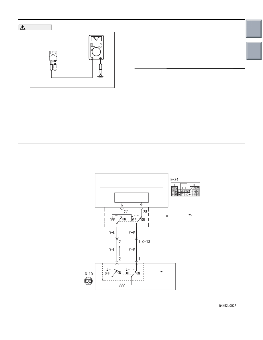
Code No.4F: Curtain air bag module (squib) (LH) system (short-circuited to the earth)
AC303709
2
1
AG
C-13
Curtain air bag module (LH)
side connector (rear view)
AC510222
CURTAIN AIR BAG
MODULE (SQUIB)
(LH)
AIR BAG
DRIVE CIRCUIT
SRS-ECU
MICRO COMPUTER
Wire colour code
B : Black LG : Light green G : Green L : Blue W : White Y : Yellow SB : Sky blue
BR : Brown O : Orange GR : Grey R : Red P : Pink V : Violet
CONNECTOR
LOCK
SWITCH
CONNECTOR
LOCK
SWITCH
NOTE
CONNECTOR
COUPLED: ON
CONNECTOR
UNCOUPLED: OFF
Curtain Air Bag Module (Squib) (LH) Circuit
AB
Main
Index
Group
TOC
TROUBLESHOOTING
SUPPLEMENTAL RESTRAINT SYSTEM (SRS)
52B-40
OPERATION
The SRS-ECU judges how severe a collision is by
detecting signals from the side impact sensors and
the side-airbag safing G-sensor. If the impact is over
a predetermined level, the SRS-ECU sends an igni-
tion signal. At this time, if the side-airbag safing
G-sensor is on, the curtain air bag module will
deploy.
DIAGNOSIS CODE SET CONDITIONS
This diagnosis code is set if the curtain air bag mod-
ule squib (LH) wire(s) are short-circuited to the earth.
PROBABLE CAUSES
• Damaged wiring harnesses or connectors
• Short to the earth in the curtain air bag module
(squib) (LH) harness
• Malfunction of the SRS-ECU
DIAGNOSIS PROCEDURE
STEP 1. Check the diagnosis code by connecting
a dummy resistor (M.U.T.-III diagnosis code).
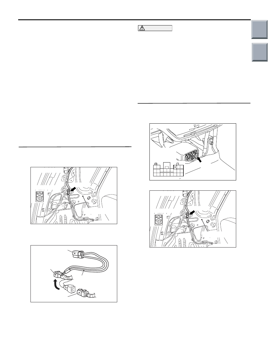
(1) Disconnect the negative battery terminal.
(2) Disconnect intermediate connector C-13
(connection between curtain air bag wiring
harness and instrument panel wiring harness).
(3) Connect special tool dummy resistor (MB991865)
to special tool resistor harness (MB991866).
CAUTION
Do not insert a test probe into the terminal from
its front side directly as the connector contact
pressure may be weakened.
(4) Connect special tool (MB991866) to the C-13
harness side connector by backprobing.
(5) Connect the negative battery terminal.
(6) Erase diagnosis code memory, and check the
diagnosis code.
Q: Is diagnosis code 4F set?
YES :
Go to Step 2.
NO :
Go to Step 3.
STEP 2. Resistance measurement at the
SRS-ECU connector B-34.
(1) Disconnect the negative battery terminal.
(2) Disconnect SRS-ECU connector B-34.
(3) Disconnect intermediate connector C-13
(connection between curtain air bag wiring
harness and instrument panel wiring harness).
AC209027
Connector: C-13
C-13 (R)
Quarter panel
AC
Harness side
AC006042 CK
MB991866
(Resistor harness)
C-13
Intermediate h
arness side
connector
MB991865 (Dummy
resistor: 3
Ω)
C-13 Curtain air bag
module (LH) side connector
AC206285
AG
B-34 (Y)
Connector: B-34
Harness side
connector
(rear view)
343536373839404142
252627282930313233
2122
2324
AC209027
Connector: C-13
C-13 (R)
Quarter panel
AC
Harness side
Main
Index
Group
TOC
TROUBLESHOOTING
SUPPLEMENTAL RESTRAINT SYSTEM (SRS)
52B-41
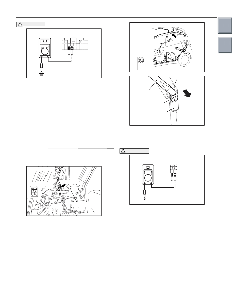
CAUTION
Do not insert a test probe into the terminal from
its front side directly as the connector contact
pressure may be weakened.
(4) Resistance measurement between B-34 harness
side connector terminals 27, 28 and body earth.
OK: Open circuit
Q: Is the check result normal?
YES :
Go to Step 4.
NO :
Repair the harness wire between SRS-ECU
connector B-34 (terminal No.27 and 28) and
harness side connector C-13 (terminal No.2
and 1).
STEP 3. Resistance measurement at the curtain
air bag harness connector C-13.
(1) Disconnect the negative battery terminal.
(2) Disconnect intermediate connector C-13
(connection between curtain air bag wiring
harness and instrument panel wiring harness).
(3) Disconnect curtain air bag harness connector
C-10. Use a flat-tipped screwdriver to pull out the
locking button at the harness side connector, and
then disconnect the connector.
CAUTION
Do not insert a test probe into the terminal from
its front side directly as the connector contact
pressure may be weakened.
(4) Resistance measurement between C-13 curtain
air bag module (LH) side connector terminals 1, 2
and body earth.
OK: Open circuit
Q: Is the check result normal?
YES :
Replace the curtain air bag module (Refer
to
NO :
Repair the harness wire between curtain air
bag module (LH) connector C-13 (terminal
No.1 and 2) and curtain air bag module
connector C-10 (terminal No.1 and 2).
AC100343
343536373839404142
252627282930313233
2122
2324
B-34 Harness side connector
(rear view)
AL
AC209027
Connector: C-13
C-13 (R)
Quarter panel
AC
Harness side
AC401577
Connector: C-10
C-10 (B)
Harness side
connector
(front view)
AC
AC208384BK
C-10
Curtain air bag
module connector
Flat-tipped
screwdriver
Locking button
C-10
Harness side
connector
AC303710
2
1
AF
C-13 Curtain air bag module
side connector (rear view)
Main
Index
Group
TOC
Нет комментариевНе стесняйтесь поделиться с нами вашим ценным мнением.
Текст