DAF 95XF. Manual — part 311
5
Electrical installation
ELECTRICAL INSTALLATION
2-143
B010
30
1
1000
37
1316630/05
EL000143
4558
6
116
4558
G515
4554
!
4552
4552
4553
4550
4557
4553
4552
B073
M
1
2
A500
P
E524
1
32
D622
1
2
D623
1
2
1000
4557
4557
4553
4553
5
116
4553
2
116
4550
4550
4550
4550
4
116
4552
4558
4558
1221
9/401
1221
3
376
1221
4550
4550
17
115
2
115
4550
4552
1221
1221
1221
4555
1/122
6/122
3/122
1221
5/122
1221
1221
1
116
19
115
4555
4555
18
373
1221
2
373
1221
D851
1
34
1221
6
185
1221
D529
1
34
1221
4555
1
515
2
515
1221
4555
14
376
4552
18
115
4552
3
116
4552
C741
1
34
1221
2/122
2/122
4/122
D
115
7
116
4
515
4552
4553
D878
1010
1000
1010
1000
E062
10A
1
23456789
1
0
1
1
1
2
1
3
1
4
1
5
1
6
1
7
1
8
1
9
2
0
2
1
2
2
2
3
2
4
2
5
2
6
2
7
2
8
2
9
3
0
3
1
3
2
3
3
3
4
3
5
3
6
3
7
3
8
3
9
4
0
4
1
4
2
4
3
4
4
4
5
4
6
4
7
4
8
4
9
5
0
5
1
5
2
5
3
S1
87A
15
52
D503
87
31
E507
1
3
2
G052
1
2
85
86
G066
30
85
86
87A
8
7
D611
3
4
5
1
D612
D613
2
1
B072
2
1
B071
C739
3
1
7
0l
ll
13
376
10
ǹ 9711
5
ELECTRICAL INSTALLATION
Electrical installation
2-144
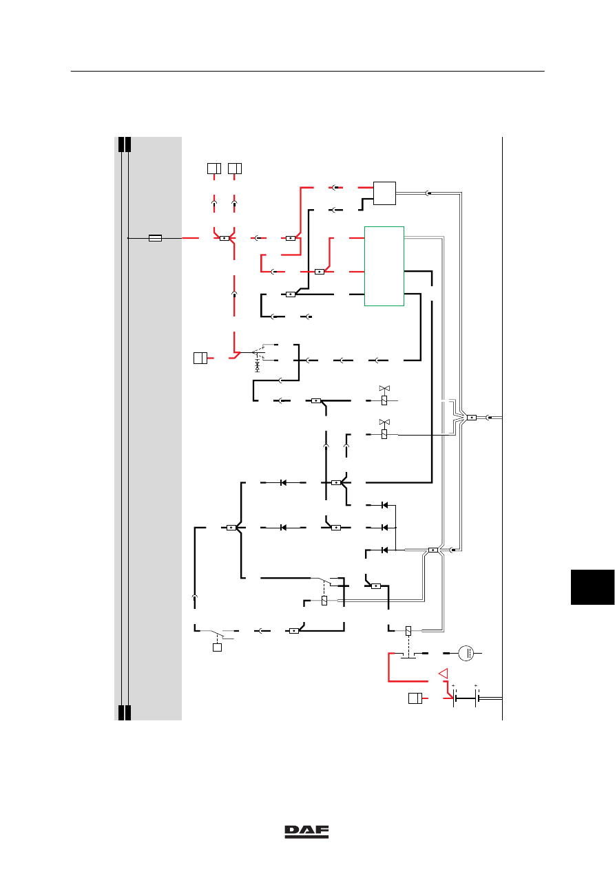
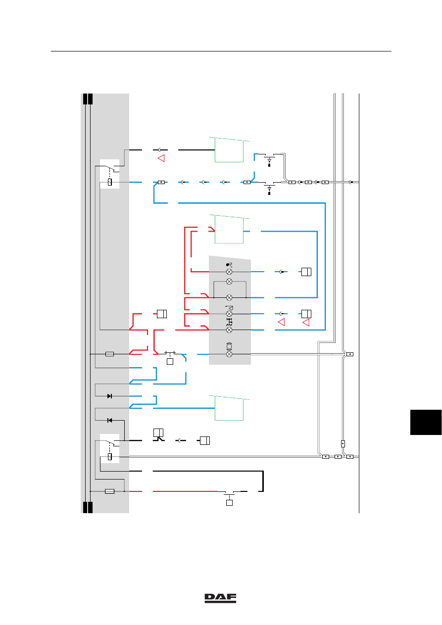
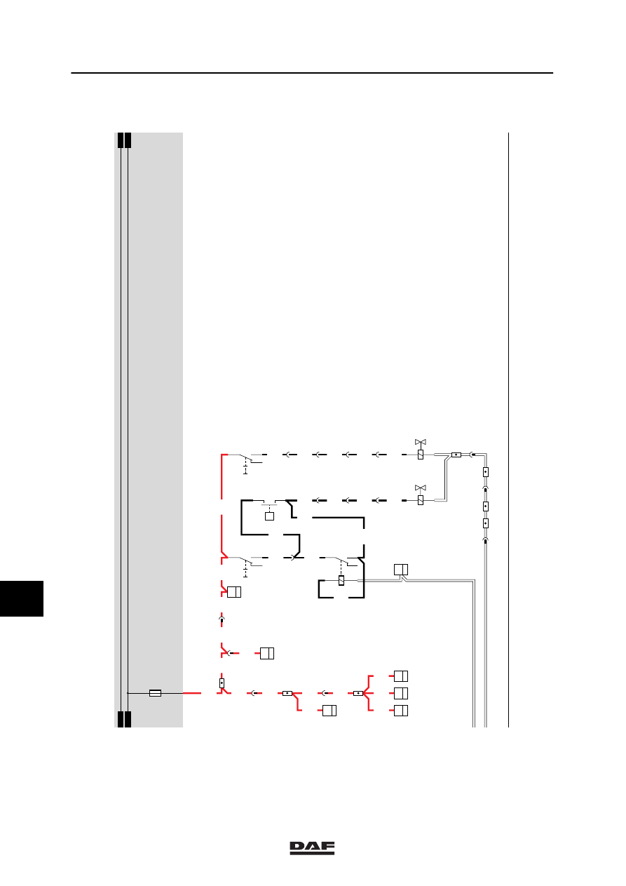
38. GEARBOX PTO
Operation
If the contact is activated, a voltage is applied to
the electronic unit CWS (D853) pin 14.
A voltage is then also applied to C750 and C751
(PTO control switch) through fuse E016 and
wire 1217.
If the PTO control switch (C750) is engaged, a
voltage will be applied to E570 (control switch
clutch/PTO N/10) and to contact 3 of relay
G259. Switch E570 will make a connection
between contacts 1 and 2. As a result, both
relay G259 will be activated and a voltage will
be applied to connection point 1 (through wire
4596) of B245. The relay will establish a
connection to connection point 1 of valve B245
through contacts 3 and 5.
If the PTO control switch (C751) is engaged, a
voltage will be applied to B246 (PTO control
valve). As a result, valve B246 is activated.
VARIANTS
Location
25 In the case of 4x2, connector 373 and unit
D851 are used.
In the case of 6x2, connector 445 and unit
D802 are used.
45 This depends on the speed-limiter type.
Connector 378 is used if the E-gas system
is applied.
Connector 433 is used if the ASL-G is
applied.
Connector 434 is used if the ASL-V is
applied.
10
ǹ 9711
5
Electrical installation
ELECTRICAL INSTALLATION
2-145
38
1316630/05
EL000144
14/401
5/401
7/402
1209
4602
4602
6/402
8/402
C020
1
14
4601
26/401
32/401
3475
D759
1
14
4601
22
115
4601
7/200
8/200
20/200
1211
1211
1211
9/200
1211
3475
34/401
3402
12/400
3402
3402
5/200
14/400
16/400
3432
4/200
4
373
3432
!
!
D851
25
34
3403
15/200
3/200
3410
15/201
3438
1/202
32
115
3438
F033
2
6
3410
3410
1211
1211
1211
3403
3402
1211
1211
13/400
12
115
3410
3
118
3410
3410
1
491
3410
3410
D
115
3
491
8
118
3452
7
378
3452
!
1211
D806
1
27
1
23456789
1
0
1
1
1
2
1
3
1
4
1
5
1
6
1
7
1
8
1
9
2
0
2
1
2
2
2
3
2
4
2
5
2
6
2
7
2
8
2
9
3
0
3
1
3
2
3
3
3
4
3
5
3
6
3
7
3
8
3
9
4
0
4
1
4
2
4
3
4
4
4
5
4
6
4
7
4
8
4
9
5
0
5
1
5
2
5
3
D853
14/
396
9/
396
F000
2
1
P
E511
2
1
P
F087
2
1
F088
2
1
D550
13/
396
D591
19/
333
D878
E035
10A
30
86
85
87A
87
G036
M
E013
10A
1209
D722
3475
D721
3402
4601
3
2
1
45
G240
3402
1211
1010
1000
1010
1000
D852
P
L
!
STOP
10
ǹ 9711
5
ELECTRICAL INSTALLATION
Electrical installation
2-146
38
1316630/05
EL000145
13/401
1217
54
55
56
57
58
59
60
61
62
63
64
65
66
67
68
69
70
71
72
73
74
75
76
77
78
79
80
81
82
83
84
85
86
87
88
89
90
91
92
93
94
96
96
97
98
99
100
101
102
103
104
105
106
1217
D749
5
15
1217
1
115
1217
1217
1
118
1217
1217
E501
2
12
1217
1217
B079
1
13
1217
F006
1
15
2
376
1217
3
176
1217
1217
D748
5
15
1217
1217
14
176
4594
4594
4596
4596
15
176
4595
4595
3
282
4595
9
285
4595
6
525
4595
4596
4
282
4596
10
285
4596
5
525
4596
4594
4596
8
525
12
285
18
281
G015
86
1
E561
2
13
D878
E016
10A
1010
1000
1010
1000
C750
5
71
0I
C751
5
71
0I
G259
3
1
24
5
2
1
B246
2
1
B245
E570
2
1
P
10
ǹ 9711
Нет комментариевНе стесняйтесь поделиться с нами вашим ценным мнением.
Текст