DAF 95XF. Manual — part 308
5
Electrical installation
ELECTRICAL INSTALLATION
2-131
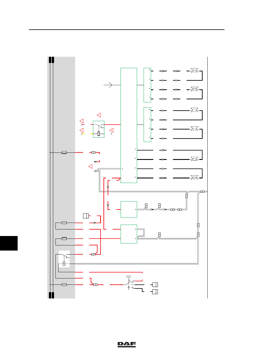
35. CONVERTER/RADIO
The following description of operation and
installation is merely advisory.
Read the manufacturer’s installation
instructions supplied with the radio.
If the contact switch (C539) is activated in
accessory position 1, pin 1 is connected to pin 6
(wire 1100 to wire 1130). As a result, relay G178
is activated. A voltage is now applied to pin 2 of
the voltage converter (D525) through the
contacts of relay G178 and fuse E027.
The converter reduces this voltage to a 12V
voltage and applies it to point 4 (D525).
This 12V voltage is fed to the radio (B185)
through wire 1108.
The radio is equipped with one antenna
connection and two loudspeaker outputs used to
connect loudspeakers B024 and B025. Two
filters for the loudspeakers can also be
connected to the radio. To each of these filters
(B186 en B187) two loudspeakers can be
connected (B178, B179 and B180 and B181).
The 12V output (pin 4) of the converter (D525)
can also be connected to a CB transmitter
(B026) to provide it with a supply voltage.
VARIANTS
Location
29 The converter should be connected to the
existing wiring to feed the memory function
(wire 1107). This can be done using a
voltage converter. This converter can be
obtained as an accessory.
37 Wire No. 2630. This wire should be
connected to one of the control lighting
switch wires.
31 Wire No. 1108. This wire should be
connected to wire 1108 coming from the
24/12V converter.
10
ǹ 9711
5
ELECTRICAL INSTALLATION
Electrical installation
2-132
1316630/05
EL000139
35
15/402
19/402
20/402
3/402
10/403
1/402
1/412
2/412
4/412
6/412
1100
1130
12/403
1130
1100
1100
1106
1108
4540
4540
12
185
B024
4542
4542
13
185
4541
4541
7
187
B025
B178
B179
4543
4543
8
187
4827
4827
1
194
4828
4828
2
194
4829
4829
3
194
4830
4830
4
194
B180
B181
4831
4832
4833
4834
4001
G015
85
1
4002
B010
50
1
1147
1147
5
194
6
194
7
194
8
194
4831
4832
4833
4834
4831
4832
4833
4834
17
194
18
194
19
190
20
190
32/400
1147
34/400
1110
1
176
C725
5
22
1110
3
190
1108
1108
3/427
1/427
4/427
2/427
3
189
1108
1108
7
190
12
194
15/403
1107
C539
L2
B186
L2
L1
L1
R2
B187
R2
R1
R1
24V
D525
12V
B026
12V
2
1
12V
1
2V
B185
LL
R
R
8/424
7/424
!
2
426
4
426
1107
D878
E037
15A
30
86
85
87A
8
7
G178
1100
1147
1130
E027
10A
1010
1000
1010
1000
1147
E052
10A
E028
15A
1
23456789
1
0
1
1
1
2
1
3
1
4
1
5
1
6
1
7
1
8
1
9
2
0
2
1
2
2
2
3
2
4
2
5
2
6
2
7
2
8
2
9
3
0
3
1
3
2
3
3
3
4
3
5
3
6
3
7
3
8
3
9
4
0
4
1
4
2
4
3
4
4
4
5
4
6
4
7
4
8
4
9
5
0
5
1
5
2
5
3
1108
2630
!
!
!
G231
30
85
86
87A
8
7
!
10
ǹ 9711
5
Electrical installation
ELECTRICAL INSTALLATION
2-133
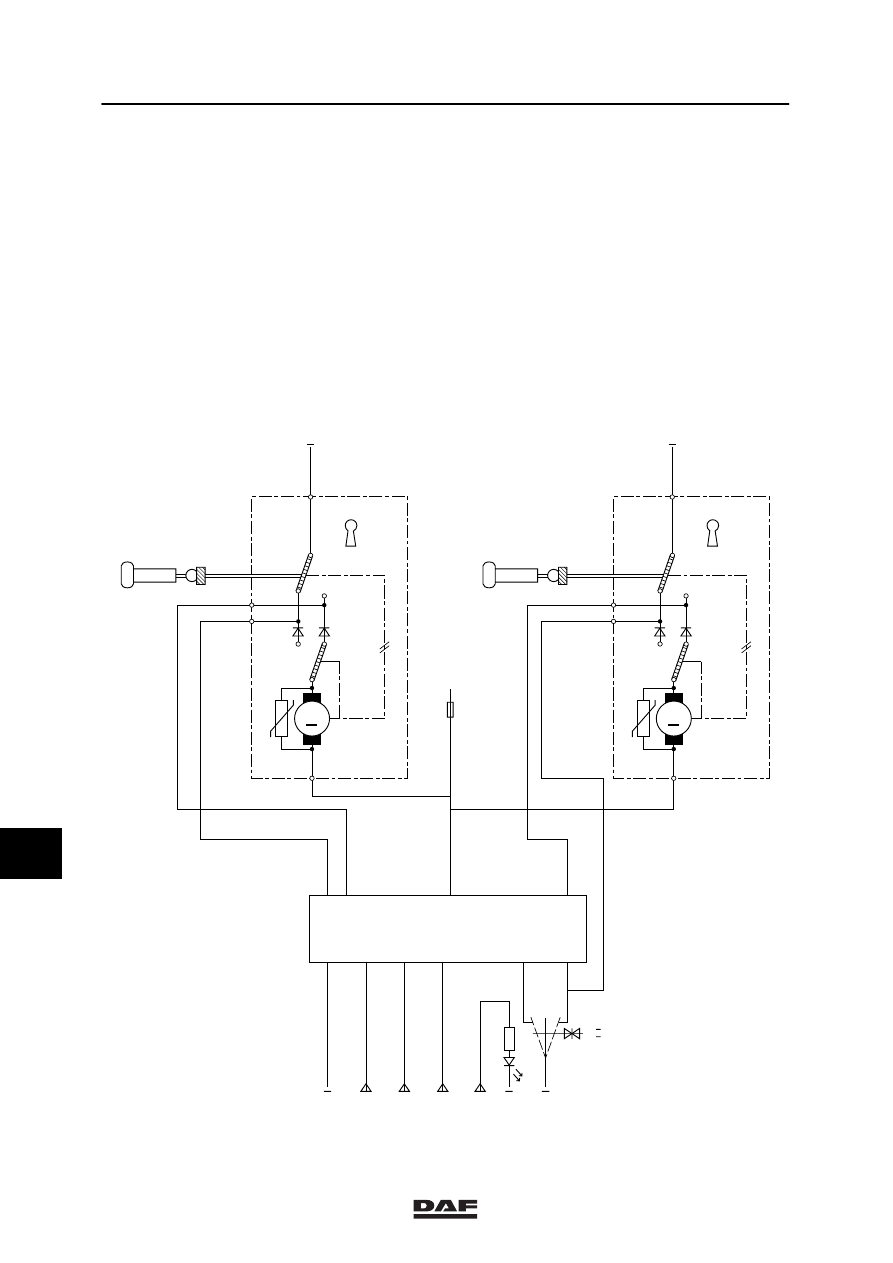
36 AUTOMATIC WINDOWS / ROOF HATCH / CENTRAL DOOR LOCKING
AUTOMATIC WINDOWS, DRIVER’S SIDE (OPENING)
(Switch in door panel, driver’s side)
If the automatic window switch (C745) is
activated and a connection is made (contacts 2
and 4), relay G030 will be activated through fuse
E044 and switch C745 (wire 4526). As a result,
a supply voltage is applied through fuse E034 to
connection point 2 of the motor (B003). The
other connection point (1) is connected to earth
through relay G031. The motor will start
operating counter-clockwise and the automatic
window on driver’s side will open.
AUTOMATIC WINDOWS, DRIVER’S SIDE (CLOSING)
(Switch in door panel, driver’s side)
If the automatic window switch (C745) is
activated and a connection is made (contacts 4
and 1), relay G031 will be activated through fuse
E044 and switch C745 (wire 4527). As a result,
a supply voltage is applied through fuse E034 to
connection point 1 of the motor (B003). The
other connection point (2) is connected to earth
through relay G030. The motor will start
operating clockwise and the automatic window
on driver’s side will close.
AUTOMATIC WINDOWS, CO-DRIVER’S SIDE (OPENING)
(Switch in door panel, driver’s side)
If the automatic window switch (C743) is
activated and a connection is made (contacts 2
and 4), relay G028 will be activated through fuse
E044 and switch C743 (wire 4522). As a result,
a supply voltage is applied through fuse E033 to
connection point 2 of the motor (B004). The
other connection point (1) is connected to earth
through relay G029. The motor will start
operating counter-clockwise and the automatic
window on co-driver’s side will open.
AUTOMATIC WINDOWS, CO-DRIVER’S SIDE (CLOSING)
(Switch in door panel, driver’s side)
If the automatic window switch (C743) is
activated and a connection is made (contacts 4
and 1), relay G029 will be activated through fuse
E044 and switch C743 (wire 4523). As a result,
a supply voltage is applied through fuse E033 to
connection point 1 of the motor (B004). The
other connection point (2) is connected to earth
through relay G028. The motor will start
operating clockwise and the automatic window
on co-driver’s side will close.
10
ǹ 9711
5
ELECTRICAL INSTALLATION
Electrical installation
2-134
AUTOMATIC WINDOWS, CO-DRIVER’S SIDE
(Switch in door panel, driver’s side)
The automatic window control using C744 on
the co-driver’s side is similar to the automatic
window control on the driver’s side. When
switch C744 (connection between contacts 4
and 2) is engaged, relay G028 is activated
through switch C743 (contacts 5 and 2) and the
motor (B004) will open the automatic window.
When switch C744 (connection between
contacts 4 and 1) is engaged, relay G029 is
activated through switch C743 (contacts 3 and
1) and the motor will operate clockwise and
close the automatic window.
The automatic windows will only function if the
contact is switched on.
K100385
M
2630
5063
2609
2600
4537
4538
1
181
5062
5061
C803
1
181
51
18
5061
0
31
30B
E182
(10A)
1000
B199
D862
DL
DO
M
31
30B
B200
CL
CO
1
5/3
B
driver co driver
door open
lock all
7
9
7
1
10
2
3
4
5
6
8
A
I
10
ǹ 9711
Нет комментариевНе стесняйтесь поделиться с нами вашим ценным мнением.
Текст