Acura RL (1996-2004 year). Manual — part 472
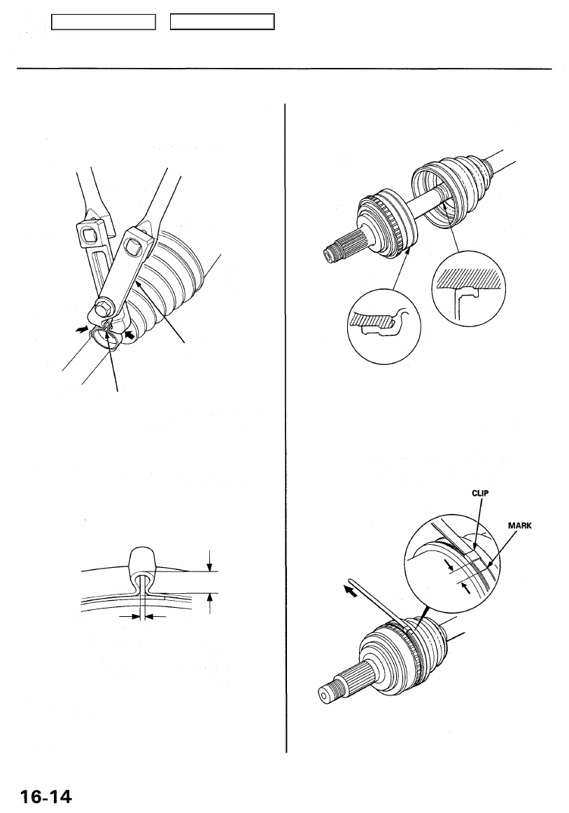
3.0 mm (0.12 in) MAX
6.0 mm (0.24 in) MAX
Reassembly (cont'd)
11. Close the ear portion of the band with a commercially
available boot band pincers Kent-Moore J-35910 or
equivalent.
Driveshafts
13. Fit the boot ends onto the driveshaft and the
outboard joint.
14. Fit the double loop boot bands onto the boot ends.
15. Pull up the slack in the band by hand.
16. Mark a position on the band 10 - 14 mm (0.4 - 0.6
in.) from the clip.
12. Check the clearance between the closed ear portion
of the band. If the clearance is not within the stan-
dard, close the ear portion of the band further.
BOOT BAND PINCERS
Kent-Moore J-35910
or equivalent
EAR PORTION
Main Menu
Table of Contents
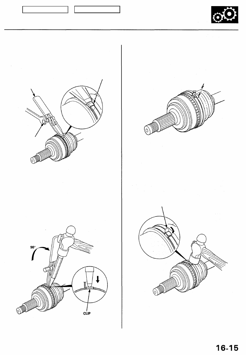
17. Thread the free end of the band through the nose
section of the commercially available boot band
tool KD-3191 or equivalent, and into the slot on the
winding mandrel.
BOOT BAND TOOL
(Commercially available)
KD-3191 or equivalent
Mark spot.
WINDING
MANDREL
18. Place a wrench on the winding mandrel of the boot
band tool, and tighten the band until the marked
spot on the band meets the edge of the clip.
19. Lift up the boot band tool to bend the free end of
the band 90° to the clip. Center punch the clip, then
fold over the remaining tail onto the clip.
21. Bend the band by tapping it down with a hammer.
NOTE: Make sure the band and the clip do not
interfere with anything, and the band does not
move. Remove any grease remaining in the sur-
rounding surfaces.
20. Unwind the boot band tool, and cut off the excess
free end of the band to leave a 5 - 10 mm (0.2 - 0.4
in) tail protruding from the clip.
BAND END
(0.2 - 0.4 in)
Main Menu
Table of Contents
3. Install a new set ring onto the driveshaft or interme-
diate shaft groove.
CAUTION: Always use a new set ring whenever
the driveshaft is being installed.
SET RING GROOVE
Driveshafts
Installation
1. Install the outboard joint into the knuckle.
KNUCKLE
4. Insert the inboard end of the driveshaft into the dif-
ferential or intermediate shaft until the set ring
locks in the groove.
NOTE: Clean the areas where the driveshaft con-
tacts the differential thoroughly with solvent or car-
buretor cleaner, and dry with compressed air.
INTERMEDIATE SHAFT
GROOVE
INBOARD JOINT
SET RING
Replace.
INBOARD JOINT
SET RING
Replace.
GROOVE
DIFFERENTIAL
5. Install the knuckle onto the lower arm, then tighten
the castle nut, and install a new cotter pin.
NOTE: Wipe off the grease before tightening the
nut at the ball joint.
CAUTION:
• Be careful not to damage the ball joint boot.
• Torque the castle nut to the lower torque speci-
fication, then tighten it only far enough to align
the slot with the pin hole. Do not align the nut
by loosening it. Install a new cotter pin.
CASTLE NUT
14 x 2.0 mm
69 - 78 N-m
(7.0 - 8.0 kgf-m,
51 - 58 Ibf-ft)
COTTER PIN
Replace.
On reassembly,
bend the cotter pin
as shown.
2. Apply 0.5 - 1.0 g (0.02 - 0.04 oz) of grease to the
whole splined surface of the intermediate shaft.
NOTE: After applying grease, remove the grease
from the splined grooves at intervals of 2 - 3 splines
and from the set ring groove so air can bleed from
the inboard joint.
SET RING
Replace.
OUTBOARD JOINT
Main Menu
Table of Contents

6. Install the damper fork over the driveshaft and onto
the lower arm. Install the damper in the damper
fork so the aligning tab is aligned with the slot in
the damper fork.
ALIGNING TAB
DAMPER FORK
FLANGE BOLT
10 x 1.25 mm
43 N-m (4.4 kgf-m, 32 Ibf-ft)
SELF-LOCKING NUT
12 x 1.25 mm
69 N-m (7.0 kgf-m, 51 Ibf-ft)
Replace.
7. Loosely install the flange bolts and the new self-
locking nut.
NOTE: The bolts and nut should be tightened with
the vehicle's weight on the damper.
8. Apply engine oil to the seating surface of the new
spindle nut.
WHEEL NUT 12 x 1.5 mm
108 N-m (11.0 kgf-m, 80 Ibf-ft)
SPINDLE NUT 24 x 1.5 mm
245 N-m (25.0 kgf-m, 181 Ibf-ft) Replace.
NOTE: After tightening, use a drift to
stake the spindle nut shoulder against the driveshaft.
9. Install a new spindle nut, then tighten the nut.
10. Install the front wheel with the wheel nuts.
NOTE: Before installing the wheel, clean the mating
surfaces of the brake disc and the wheel.
11. Tighten the flange bolts and the new self-locking
nut with the vehicle's weight on the damper.
12. Refill the differential with recommended oil (see
).
13. Check the front wheel alignment, and adjust it if
necessary (see
).
FRONT WHEEL
Main Menu
Table of Contents
Нет комментариевНе стесняйтесь поделиться с нами вашим ценным мнением.
Текст