Acura RL (1996-2004 year). Manual — part 53
+
–
35-3
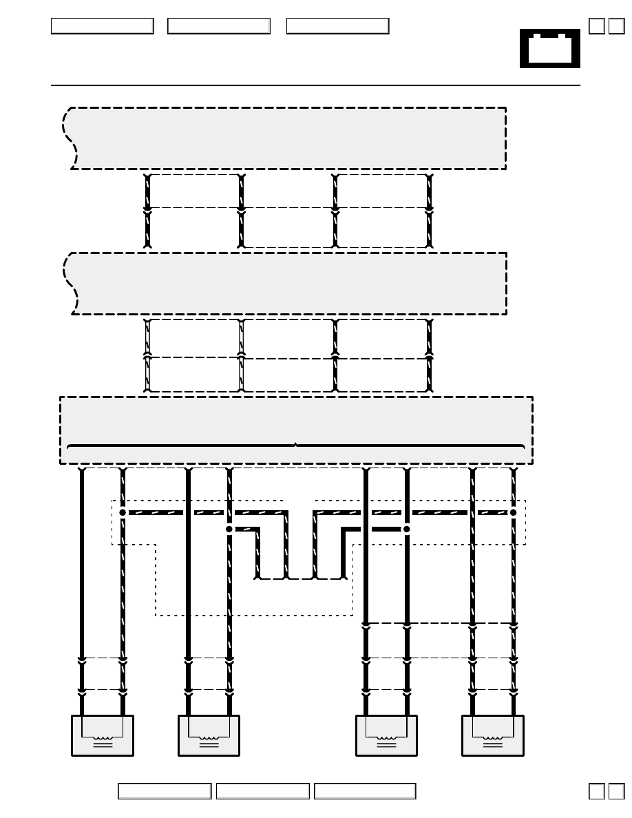
Traction Control System (TCS) (’96-’99)
‘96-‘97
C201
C215
POWERTRAIN
CONTROL
MODULE
(PCM)
TCS
CONTROL
UNIT
(
*
6)
2
)
BRN
1
(
*
7)
3
)
GRN/BLU
2
ABS
CONTROL
UNIT
LEFT
FRONT
WHEEL
SENSOR
BRN
BLK
BLK
GRN/BLU
C326
C309
(BARO)
Barometric pressure
sensor input
Right front wheel
sensor input
(FRP)
(VREF)
Voltage
reference input
Left front wheel
sensor input
(FLP)
(TC-STB)
Traction control
standby input
Right rear wheel
sensor input
(RRP)
(TC-INH)
Traction control
inhibit input
Left rear wheel
sensor input
(RLP)
Speed sensor inputs
Barometric
sensor output
signal
(BARO OUT)
Voltage
reference
(VREF)
Traction
control
standby
(TCSTB)
Traction
control
inhibit
(TCINH)
(FRP)
Right front wheel
sensor output
(FLP)
Left front wheel
sensor output
(RRP)
Right rear wheel
sensor output
(RLP)
Left rear wheel
sensor output
A
(B
*
)
20
)
(
*
15)
GRY/BLK
C444
7
GRY/BLK
A
5
18
)
(
*
13)
GRY/WHT
3
GRY/WHT
7
6
)
(
*
5)
WHT/GRN
5
WHT/GRN
1
4
)
(
*
3)
WHT/RED
6
WHT/RED
3
A
8
C444
4
LT GRN/RED
C
10
13
PNK/BLK
12
11
BLU/WHT
13
1
GRN/ORN
D
4
3
(
*
8)
4
)
GRN
1
(
*
9)
5
)
GRN/BLK
2
RIGHT
FRONT
WHEEL
SENSOR
GRN
BLK
BLK
GRN/BLK
17
18
(
*
18)
14
)
GRY
1
(
*
17)
13
)
LT BLU
2
LEFT
REAR
WHEEL
SENSOR
GRY
BLK
BLK
LT BLU
C724
3
4
11
12
(
*
20)
16
)
BLU/YEL
1
(
*
19)
15
)
GRN/YEL
2
RIGHT
REAR
WHEEL
SENSOR
BLU/YEL
BLK
BLK
GRN/YEL
C669
C725
1
2
C413
9
10
LT GRN/RED
PNK/BLK
BLU/WHT
GRN/ORN
4
GRN/
BLK
ABS INSPECTION
CONNECTOR
1
GRN/
BLU
5
GRN/
YEL
2
LT
BLU
GRN/BLU
GRN/BLK
LT BLU
GRN/YEL
GRY
LT BLU
BLU/YEL
GRN/YEL
B
B
(FLW (-))
(FLW (+))
(FRW (–))
(FRW (+))
(RLW (–))
(RLW (+))
(RRW (–))
(RRW (+))
*
= ‘98-‘99
2004 American Honda Motor Co., Inc.
▼
▼
35-4
Traction Control System (TCS) (’96-’99)
How the Circuit Works
The traction control system is a variable system that
monitors the amount of wheel spin under different
driving conditions. During straight line acceleration,
the TCS control unit may determine that some
wheel spin is beneficial. During cornering, it may
determine to reduce wheel spin by adjusting engine
power and braking. The system is not designed to
correct for gross errors of judgment on the part of
the driver.
The TCS control unit communicates with the ABS
control unit to obtain information from the wheel
speed sensors about wheel speed and frequency of
wheel rotational vibration. The wheel rotational
vibration is used by the TCS control unit to signal
the powertrain control module (PCM) to reduce
engine power under certain rough road conditions.
The TCS control unit also communicates with the
PCM to monitor A/T gear position, throttle
position, engine rpm, atmospheric pressure, and
“TCS inhibit” information.
The TCS control unit also monitors input from the
steering angle sensor. When you turn the steering
wheel, the steering angle sensor sends a signal to
the TCS control unit which reads it as a specific
cornering radius. The TCS control unit also
determines the straight ahead position by
comparing the front wheel speed inputs from the
ABS control unit. When the left front and right front
wheels are rotating at the same speed, the car is
moving in a straight line. The TCS control unit
determines the yaw angle by comparing the actual
cornering radius provided by the wheel speed
sensor inputs to the steering angle. If required, the
control unit will signal the TCS control valve
actuator and the PCM to reduce engine power and
slow the car down to maintain the cornering radius
set by the steering angle sensor when you turned
the wheel.
The TCS control unit is a self-diagnosing component
and monitors the sensors for irregular signals.
Refer to the Service Manual (Section 19, Brakes)
for testing and troubleshooting procedures.
2004 American Honda Motor Co., Inc.
▲
▼
▲
▼
36
Vehicle Stability Assist (VSA) System
VSA OFF
SWITCH
See Power
Distribution,
page 10-7.
See Ground
Distribution,
pages 14
and 14-1.
See Ground
Distribution,
page 14-5.
See Power
Distribution,
page 10-8.
BRN/WHT
BRN/WHT
BLK/WHT
BLK/WHT
R/C MIRROR
7.5A
C402
2
5
YEL/BLK
UNDER-
DASH
FUSE/
RELAY
BOX
27
WHT/BLK
C414
13
WHT/BLK
G251
See Power Distribution,
page 10-7.
ECU
20A
C405
2
26
16
BLK/YEL
BLK/YEL
See Power
Distribution,
page 10-8.
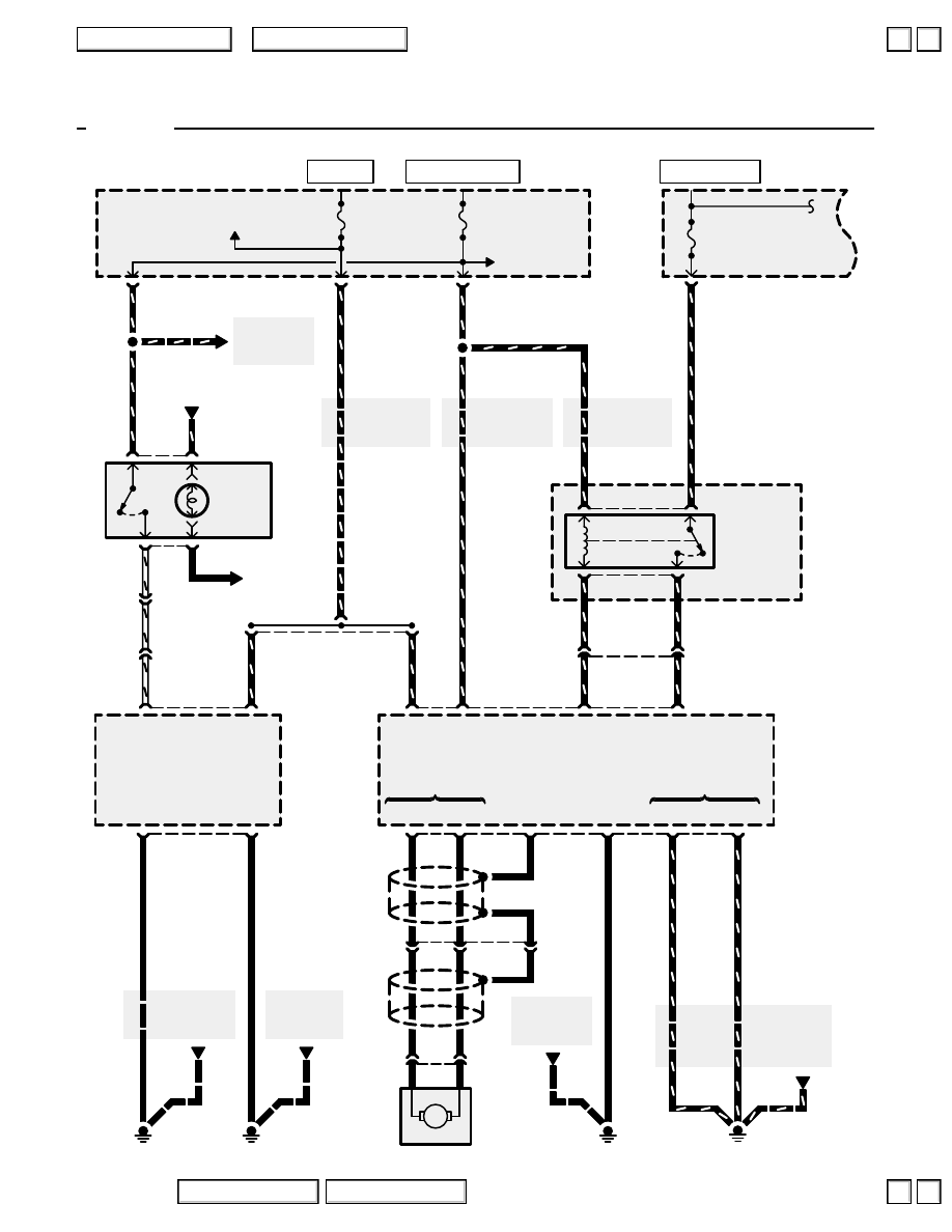
(TCS)
15A
C306
5
BLU/RED
(STM (+))
3
(STM (–))
4
Shield
(SLD)
GRN
BRN
BLK
3
2
C105
1
BLK
BLK
GRN
BRN
TCS control valve
actuator driver
1
2
C122
YEL
GRY
M
(IG1)
Power
source
SUB-
THROTTLE
MOTOR
FAIL-SAFE
RELAY
UNDER-
HOOD
RELAY
BOX C
12
(STM FSR)
Fail-safe
relay driver
14
(TB-STM)
TCS control
valve actuator
power source
9
C326
10
See Power
Distribution,
page 10-9.
3
1
5
2
10
(IG2)
Power
source
G101
1
13
BRN/BLK
BRN/BLK
BRN/BLK
BRN/BLK
(LG1)
(LG2)
Logic circuit ground
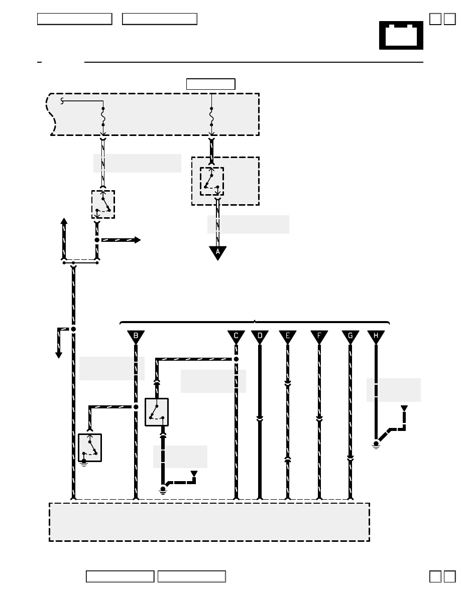
VSA
CONVERTER
UNIT
See Ground
Distribution,
page 14-13.
15
G404
BLK
VSA control
unit ground
(GND)
BLK
BLK
See Ground
Distribution,
page 14-11.
1
G401
Pump
motor
ground
(M-GND)
BLK
VSA
MODULATOR/
CONTROL
UNIT
C504
16
WHT/BLK
(VSA OFF SW)
VSA switch
input
4
RED
2
23
YEL/
BLK
(IG2)
Power
source
C502
1
BLK/
YEL
BLK/
YEL
See Power
Distribution,
page 10-9.
3
RED/BLK
1
VSA
SWITCH
LIGHT
C456
(Terminals 7-10)
YEL/BLK
BLK/YEL
BLK/YEL
BLK/YEL
YEL/BLK
Ground
(STM GND)
VSA
CONTROL
VALVE
ACTUATOR
HOT IN ON
HOT AT ALL TIMES
HOT IN ON OR START
’00-’04
2004 American Honda Motor Co., Inc.
▲
▲
+
–
36-1
Vehicle Stability Assist (VSA) System
’00-’04
BRAKE FLUID
LEVEL SWITCH
Closed with
low fluid level
See Brake System
Indicator Light,
page 71-2.
GRN/WHT
C476
See Brake System
Indicator Light,
page 71-2.
NOTE: The Gauge Relay is energized with the Ignition Switch in ON (II) or START (III). See Gauge Assembly,
page
See Ground
Distribution,
page 14-7.
See Power Distribution,
page 10-18.
WHT/YEL
WHT/YEL
See Gauge Assembly,
page 80-5 or 80-9.
WHT/RED
WHT/RED
METER
15A
C307
1
RED/YEL
GAUGE
RELAY
UNDER-HOOD
RELAY BOX C
1
2
STOP
HORN
20A
C301
5
BRAKE PEDAL
POSITION SWITCH
Closed with
pedal pressed
4
3
UNDER-HOOD
FUSE/RELAY
BOX
C464
(Terminals
14-16)
GRN/WHT
GRN/WHT
GRN/WHT
YEL/BLU
C504
14
BLU/WHT
C476
3
LT GRN/
RED
C477
4
)
(’00-’03
3)
BLK
C321
G301
BLK
BLK
C322
GRN/
RED
GRN/WHT
BLK
(VSA)
VSA
indicator
driver
33
(STOP)
Brake
input
32
GRN/WHT
See Automatic
Transmission
Controls,
Wiper/Washer
GRN/
WHT
GRN/
WHT
GRN/WHT
GRN/RED
PARKING
BRAKE
SWITCH
Closed
with
parking
brake
applied
GRN/RED
GRN/RED
(PARK)
Parking
brake
input
38
GRN/RED
G401
See Ground
Distribution,
page 14-11.
BLK
BLU/WHT
LT GRN/
RED
(ABS)
ABS
indicator
driver
17
(INFO)
VSA
activation
indicator
driver
7
YEL/BLU
C414
8
YEL/BLU
GRY
(EBD)
Brake
system
indicator
driver
18
14
GRY
GRN/RED
(BFL)
Brake
fluid
level
input
36
GRN/WHT
VSA
MODULATOR/
CONTROL
UNIT
From page 36-6 or 36-7
To page
36-6 (’00-’03)
or 36-7 (’04)
HOT AT ALL TIMES
2004 American Honda Motor Co., Inc.
Нет комментариевНе стесняйтесь поделиться с нами вашим ценным мнением.
Текст