Acura RL (1996-2004 year). Manual — part 546
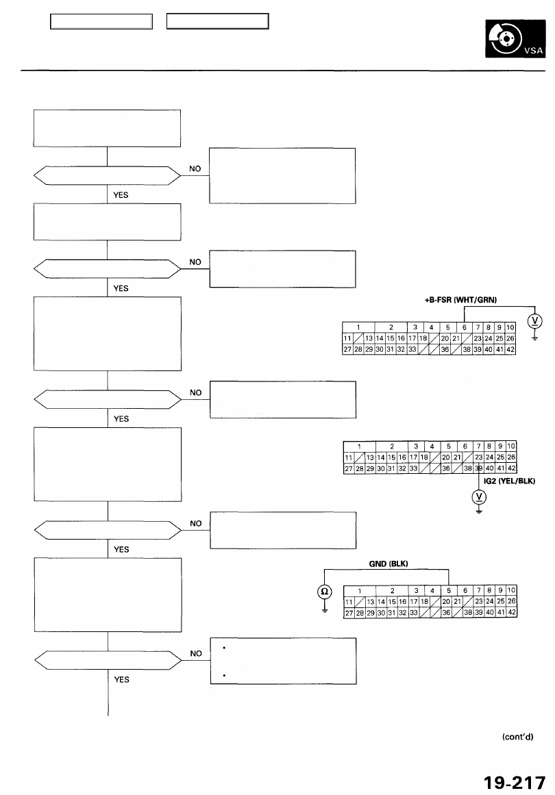
VSA System Indicator Does Not Go Off
Check the VSA (20 A) fuse in the
under-hood fuse/relay box, and
reinstall the fuse if it is OK.
Is the fuse OK?
Check the R/C MIRROR (7.5 A) fuse
in the under-dash fuse/relay box,
and reinstall the fuse if it is OK.
Is the fuse OK?
Check for an open in the +B FSR
circuit:
1. Disconnect the VSA control
unit 42P connector.
2. Measure the voltage between
terminal No. 6 and body
ground.
Is there battery voltage?
Is there battery voltage?
Check for an open in the GND cir-
cuit:
1. Turn the ignition switch OFF.
2. Check for continuity between
the VSA control unit 42P con-
nector terminal No. 5 and body
ground.
Is there continuity?
Replace the fuse, and recheck. If
the fuse is blown, check for a
short to body ground in this fuse
circuit. If the circuit is OK, replace
the VSA modulator-control unit.
Replace the fuse, and recheck. If
the fuse is blown, check for a short
to body ground in this fuse circuit.
VSA CONTROL UNIT 42P CONNECTOR
Wire side of female terminals
Repair open in the wire between
the VSA (20 A) fuse and the VSA
control unit.
Repair open in the wire between
the R/C MIRROR (7.5 A) fuse and
the VSA control unit.
Repair open in the wire between
the VSA control unit and body
ground.
Repair poor ground (G251).
Check for an open in the IG2 cir-
cuit:
1. Turn the ignition switch ON (II).
2. Measure the voltage between
the VSA control unit 42P con-
nector terminal No. 23 and
body ground.
Main Menu
Table of Contents
Troubleshooting
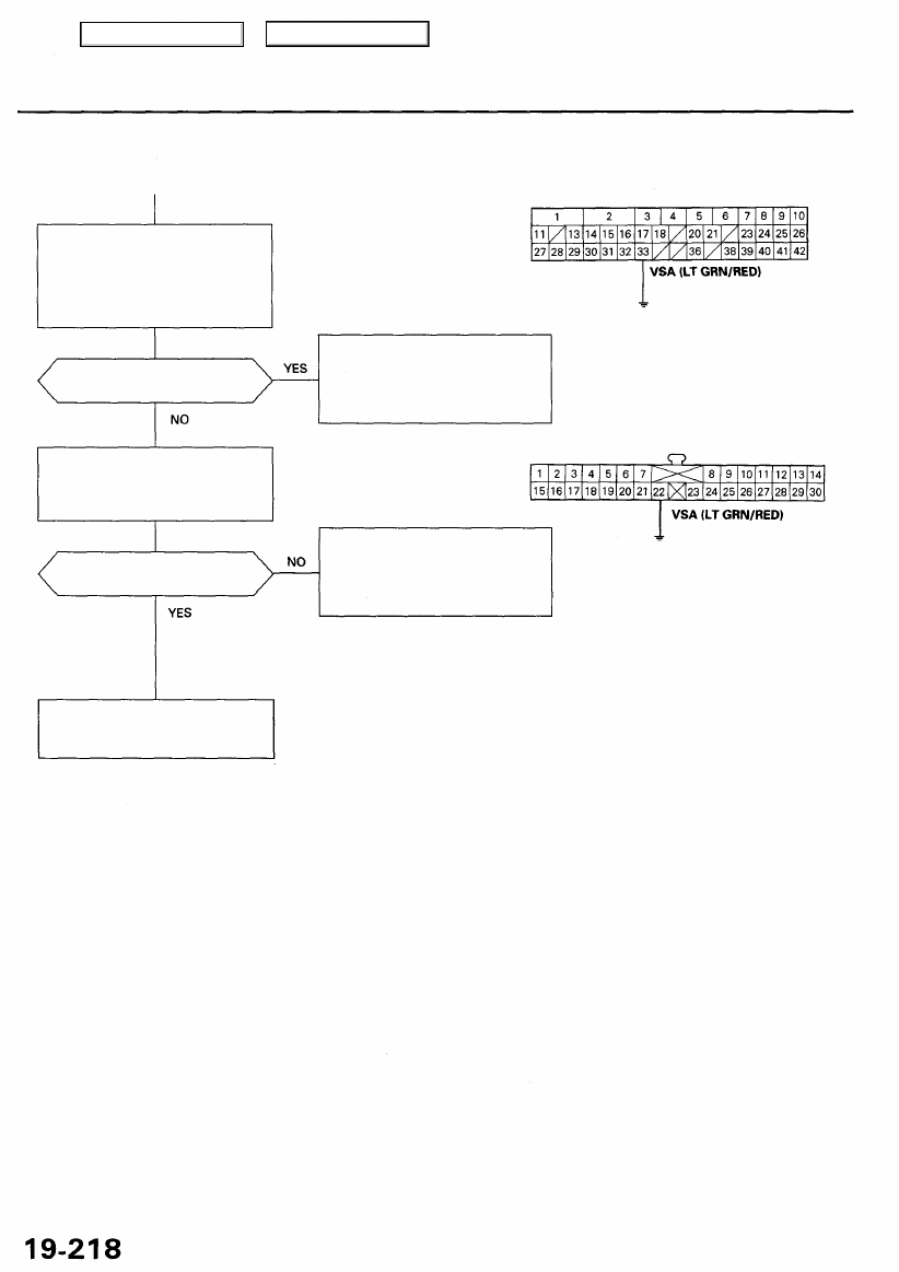
VSA System Indicator Does Not Go Off (cont'd)
Check the VSA control unit:
1. Turn the ignition switch ON (II).
2. Connect the VSA control unit
42P connector terminal No. 33
and body ground with a
jumper wire.
Does the VSA system indica-
tor go off?
Check the gauge assembly:
Connect the gauge assembly 30P
connector terminal No. 22 and
body ground with a jumper wire.
Does the VSA system indica-
tor go off?
Repair open in the wire between
the gauge assembly and the VSA
control unit.
VSA CONTROL UNIT 42P CONNECTOR
Check for loose terminals in the
VSA control unit 42P connector.
If necessary, substitute a known-
good VSA modulator-control
unit, and recheck.
Wire side of female terminals
GAUGE ASSEMBLY 30P CONNECTOR
Check for loose terminals in the
gauge assembly 30P connector.
If the connector is OK, replace
the printed circuit board in the
gauge assembly.
JUMPER
WIRE
Terminal side of female terminals
JUMPER
WIRE
Main Menu
Table of Contents
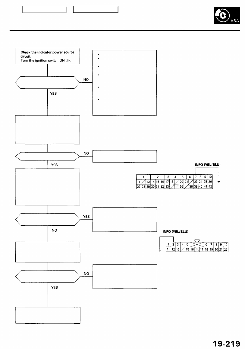
VSA Activation Indicator Does Not Come On
Does the brake system indica-
tor come on?
Check the VSA activation indica-
tor:
1. Turn the ignition switch OFF.
2. Check the VSA activation indi-
cator bulb in the gauge assem-
bly.
Is the bulb OK?
Check the VSA control unit:
1. Disconnect the VSA control
unit 42P connector.
2. Turn the ignition switch ON (II).
3. Connect the VSA control unit
42P connector terminal No. 7
and body ground with a
jumper wire.
Does the VSA activation
indicator come on?
Check the gauge assembly:
Connect the gauge assembly 22P
connector terminal No. 2 and
body ground with a jumper wire.
Does the VSA activation
indicator come ON?
Repair open in the wire between
the gauge assembly and the VSA
control unit.
Gauge relay stuck OFF.
Blown METER (15 A) fuse in the
under-hood fuse/relay box.
Blown METER (7.5 A) fuse in
the under-dash fuse/relay box.
Repair open in the wire between
the METER (15 A) fuse and the
gauge assembly.
Repair open in the wire between
the METER (7.5 A) fuse and body
ground.
Replace the under-hood fuse/
relay box or under-dash fuse/
relay box. (Open circuit inside
the box.)
Replace the VSA activation indi-
cator bulb.
VSA CONTROL UNIT 42P CONNECTOR
JUMPER
WIRE
Check for loose terminals in the
VSA control unit 42P connector.
If necessary, substitute a known-
good VSA modulator-control
unit, and recheck.
JUMPER
WIRE
Wire side of female terminals
GAUGE ASSEMBLY 22P CONNECTOR
Wire side of female terminals
Check for loose terminals in the
gauge assembly 22P connector.
If the connector is OK, replace
the printed circuit board in the
gauge assembly.
Main Menu
Table of Contents
Troubleshooting
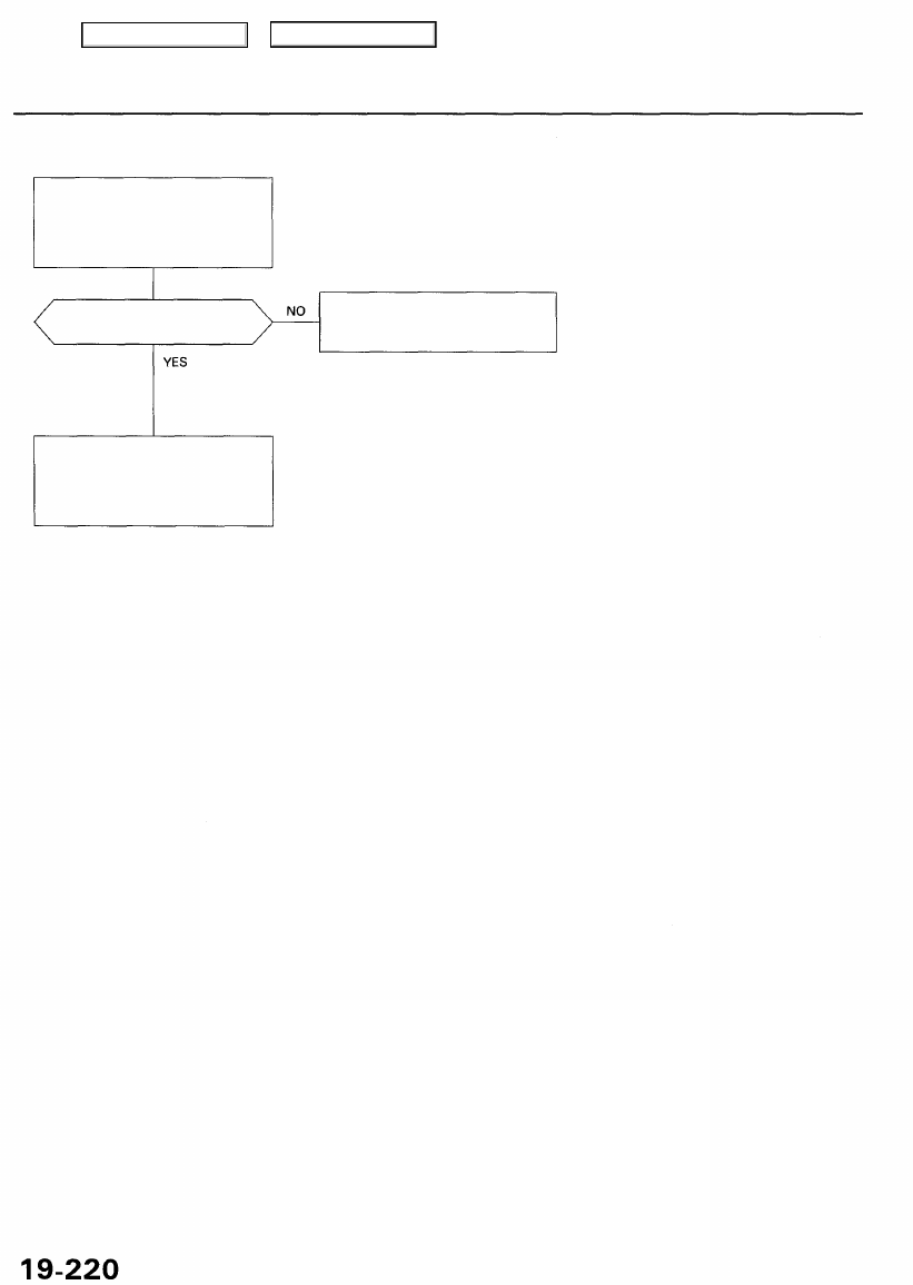
VSA Activation Indicator Does Not Go Off
Check for a short to body ground
in the INFO circuit:
1. Disconnect the VSA control
unit 42P connector.
2. Turn the ignition switch ON (II).
Does the VSA activation
indicator go off?
Repair short to body ground in the
wire between the gauge assembly
and the VSA control unit.
Check for loose terminals in the
VSA control unit 42P connector.
If necessary, substitute a known-
good VSA modulator-control
unit, and recheck.
Main Menu
Table of Contents
Нет комментариевНе стесняйтесь поделиться с нами вашим ценным мнением.
Текст