Acura RL (1996-2004 year). Manual — part 638
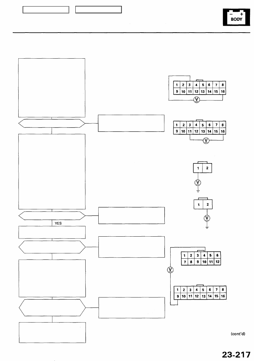
Flowchart No. 6
Power Seat Rear Up-down Switch:
Check for voltage between the seat
control unit 16P connector B3 and
B16 terminals with the rear up-
down switch pushed up. Check for
voltage between the seat control
unit 16P connector B11 and B16
terminals with the rear up-down
switch pushed down.
There should be 1 V or less with
the switch pushed and 4 V or more
with the switch in the neutral posi-
tion.
Are voltages as specified?
NO
• Open or short in the wires
• Faulty rear up-down switch
• Faulty seat control unit
YES
Power Seat Rear Up-down Motor:
Disconnect the 2P connector from
the driver's power seat rear up-
down motor. Check for voltage
between the driver's power seat
rear up-down motor 2P connector
No. 1 terminal and body ground
with the rear up-down switch
pushed up. Check for voltage
between the driver's power seat
rear up-down motor 2P connector
No. 2 and body ground with the
rear up-down switch pushed
down. There should be 10 V or
more with the switch pushed and
O V with the switch in the neutral
position.
Are voltages as specified?
NO
• Open or short in the wires
• Faulty rear up-down switch
• Faulty seat control unit
Test the driver's power seat rear
).
Does the motor run smoothly
and without noise?
• Open or short in the GRN or
BRU/GRN wire between motor
and the 2P connector.
• Faulty rear up-down motor
NO
YES
Check for voltage between the
seat control unit 16P connector
B9 terminal and 12P connector
A4 terminal while operating the
rear up-down motor upward and
downward.
NOTE: All DPMS connectors must
be connected.
• Open or short in the wires
• Faulty rear up-down position
sensor
• Faulty seat control unit
NO
Does the voltage pulse between
1 V or less and 5 V or more with
the rear up-down motor running?
YES
Substitute a known-good seat
control unit, and recheck. If the
systems now work OK, replace
the original seat control unit.
SEAT CONTROL UNIT
16P CONNECTOR "B"
SEAT CONTROL UNIT
12P CONNECTOR "A"
NOTE: All connector views are from wire side
of female terminals.
SEAT CONTROL UNIT
16P CONNECTOR "B"
DRIVER'S POWER SEAT
REAR UP-DOWN MOTOR
2P CONNECTOR
Main Menu
Table of Contents
Driving Position Memory System (DPMS)
Troubleshooting (cont'd)
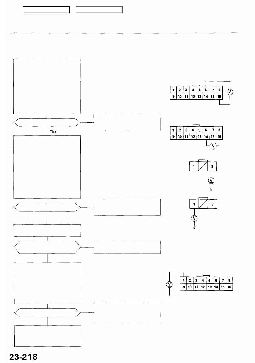
Flowchart No. 7
Steering Column Switch (Tilt):
Check for voltage between the
column control unit 16P connec-
tor B6 and B16 terminals with the
tilt-up switch pushed. Check for
voltage between the column con-
trol unit 16P connector B14 and
B16 terminals with the tilt-down
switch pushed. There should be 1
V or less with the switch pushed
and 4 V or more with the switch in
the neutral position.
Are voltages as specified?
NO
• Open or short in the wires
• Faulty steering column switch
• Faulty column control unit
Tilt Motor:
Disconnect the 3P connector from
the steering column tilt motor.
Check for voltage between the tilt
motor 3P connector No. 3 termi-
nal and body ground with the tilt-
up switch pushed. Check for volt-
age between the tilt motor 3P
connector No. 1 terminal and
body ground with the tilt-down
switch pushed. There should be
10 V or more with the switch
pushed and 1 V or less with the
switch in the neutral position.
Are voltages as specified?
NO
• Open or short in the wires
• Faulty steering column switch
• Faulty column control unit
YES
Test the steering column tilt motor
).
Does the motor run smoothly
and without noise?
Replace the steering column tilt
motor.
NO
YES
Check for voltage between the col-
umn control unit 16P connector B1
and B10 terminals. There should
be 2.5 V or more with the steering
column in the fully-up position
and 2.5 V or less with the steering
column in the fully-down position.
NOTE: All column control unit con-
nectors must be connected.
NOTE: If necessary, apply power and
ground to the tilt motor to move the col-
umn to the fully-up and fully-down posi-
tions (see page
).
• Open or short in the BLU or BRN
wires
• Faulty tilt position sensor
• Faulty column control unit
NO
Substitute a known-good column
control unit, and recheck. If the
systems now work OK, replace
the original column control unit.
Are voltages as specified?
YES
COLUMN CONTROL UNIT
16P CONNECTOR "B"
NOTE: All connector views are from wire side
of female terminals.
COLUMN CONTROL UNIT
16P CONNECTOR "B"
TILT MOTOR 3P CONNECTOR
Main Menu
Table of Contents
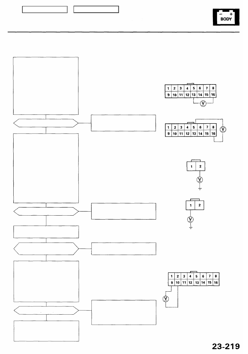
Flowchart No. 8
Steering Column Switch (Extend-
retract)
Check for voltage between the col-
umn control unit 16P connector
B13 and B16 terminals with the
extend switch pushed.
Check for voltage between the col-
umn control unit 16P connector B5
and B16 terminals with the retract
switch pushed. There should be 1
V or less with the switch pushed
and 4 V or more with the switch in
the neutral position.
• Open or short in the wires
• Faulty steering column switch
• Faulty column control unit
NO
Are voltages as specified?
YES
Extend-retract Motor:
Disconnect the 2P connector from
the steering column extend-retract
motor.
Check for voltage between the
extend-retract motor 2P connector
No. 2 terminal and body ground
with the extend switch pushed.
Check for voltage between the
extend-retract motor 2P connector
No. 1 terminal and body ground
with the retract switch pushed.
There should be 10 V or more
with the switch pushed and 1 V or
less with the switch in the neutral
position.
Are voltages as specified?
NO
• Open or short in the wires
• Faulty steering column switch
• Faulty column control unit
YES
Test the steering column extend-
).
Replace the steering column
extend-retract motor.
Does the motor run smoothly
and without noise?
YES
NO
NOTE: If necessary, apply power and
ground to the extend-retract motor to
move the column to the fully-extended
and fully-retracted position (see page
).
Check for voltage between the col-
umn control unit 16P connector B9
and B10 terminals. There should
be 2.5 V or more with the steering
column in fully extended position
and 2.5 V or less with the steering
column in fully retracted position.
NOTE: All column control unit con-
nectors must be connected.
Are voltages as specified?
NO
• Open or short in the PNK or BRN
wires
• Faulty extend-retract position
sensor
• Faulty column control unit
Substitute a known-good column
control unit, and recheck. If the
systems now work OK, replace
the original column control unit.
YES
COLUMN CONTROL UNIT
16P CONNECTOR "B"
(cont'd)
NOTE: All connector views are from wire side
of female terminals.
COLUMN CONTROL UNIT
16P CONNECTOR "B"
EXTEND-RETRACT MOTOR
2P CONNECTOR
Main Menu
Table of Contents
Driving Position Memory System (DPMS)
Troubleshooting (cont'd)
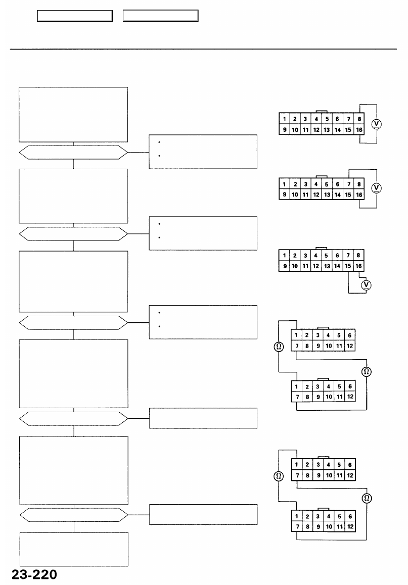
Flowchart No. 9
MEMO Button:
Check for voltage between the col-
umn control unit 16P connector B8
and B16 terminals. There should
be 1 V or less with the MEMO but-
ton pushed and 5 V or more with
the MEMO button released.
Are voltages as specified?
YES
Position Button 1:
Check for voltage between the col-
umn control unit 16P connector B7
and B16 terminals. There should be
1 V or less with the position button
1 pushed and 5 V or more with the
position button 1 released.
Are voltages as specified?
YES
Position Button 2:
Check for voltage between the
column control unit 16P connec-
tor B15 and B16 terminals. There
should be 1 V or less with the
position button 2 pushed and 5 V
or more with the position button
2 released.
Are voltages as specified?
YES
Communication Lines:
Check for continuity between the
column control unit 12P connector
A1 terminal and seat control unit
12P connector A1 terminal. Check
for continuity between the column
control unit 12P connector A7 ter-
minal and seat control unit 12P
connector A7 terminal.
Is there continuity?
YES
Communication Lines:
Check for continuity between the
column control unit 12P connec-
tor A1 terminal and mirror control
unit 12P connector A1 terminal.
Check for continuity between the
column control unit 12P connec-
tor A7 terminal and mirror control
unit 12P connector A7 terminal.
Is there continuity?
YES
Substitute a known-good column
control unit, and recheck. If the
systems now work OK, replace
the original column control unit.
NOTE: All connector views are from wire side
of female terminals.
COLUMN CONTROL UNIT
16P CONNECTOR "B"
Open or short in the BLU/YEL or
YEL/BLU wires
Faulty driving position memory
switch
COLUMN CONTROL UNIT
12P CONNECTOR "A"
Open in the LT GRN/RED or BLK/
WHT wires
SEAT CONTROL UNIT
12P CONNECTOR "A"
COLUMN CONTROL UNIT
12P CONNECTOR "A"
Open in the LT GRN/RED or BLK/
WHT wires
MIRROR CONTROL UNIT
12P CONNECTOR "A"
NO
NO
NO
NO
NO
Open or short in the YEL/WHT or
YEL/BLU wires
Faulty driving position memory
switch
Open or short in the BLU/WHT or
YEL/BLU wires
Faulty driving position memory
switch
Main Menu
Table of Contents
Нет комментариевНе стесняйтесь поделиться с нами вашим ценным мнением.
Текст