Acura RL (1996-2004 year). Manual — part 650
Rear Window Defogger
Control Unit Input Test (cont'd)
NOTE: Before testing, go to the Troubleshooting Guide (see page
). Be sure to go through self-diagnosis function
and
).
Multiplex Control Unit (Driver's):
1. Remove the under-dash fuse/relay box (see page
).
2. Remove the driver's unit from the under-dash fuse/relay box (see page
).
3. Inspect the connector and socket terminals to be sure they are all making good contact.
• If the terminals are bent, loose or corroded, repair them as necessary, and recheck the system.
• If the terminals look OK, make the following input tests at the connector and the fuse/relay box socket.
If any test indicates a problem, find and correct the cause, then recheck the system.
If all the input tests prove OK, the control unit must be faulty; replace it.
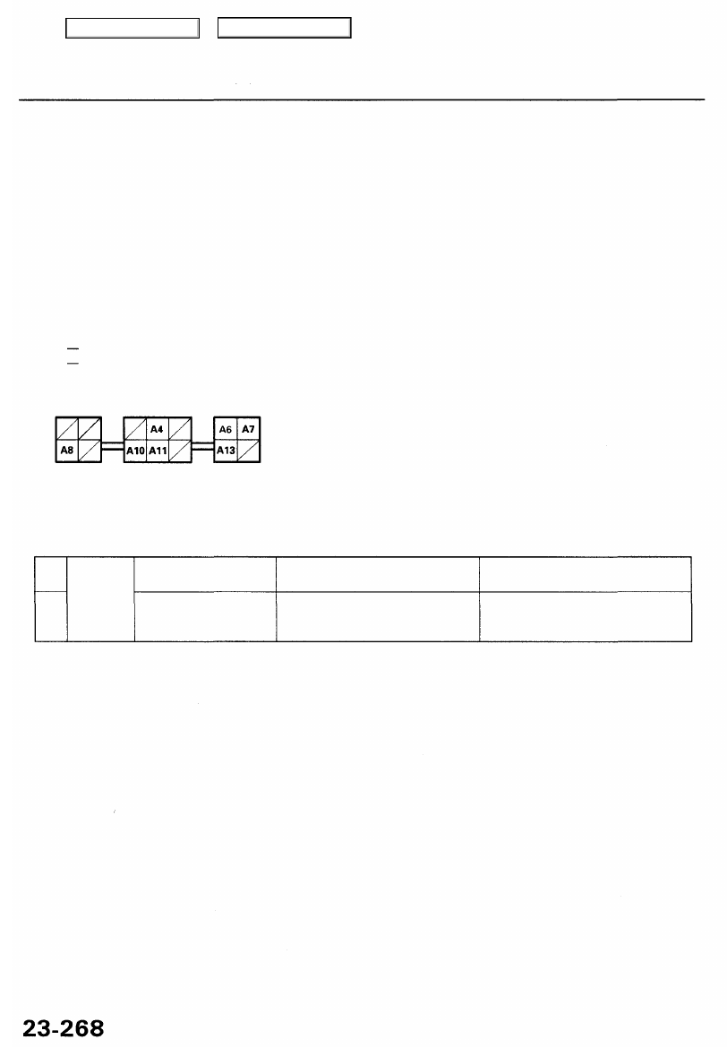
Fuse/relay
box socket
Cavity Wire Test condition Test: Desired result Possible cause if result is not obtained
Fuse/relay
box socket
A8
A13
Ignition switch ON (II)
Under all conditions
Check for continuity to ground:
There should be continuity
Check for voltage to ground:
There should be battery voltage.
• Blown No. 13 (7.5 A) fuse in the
under-dash fuse/relay box
• An open in the wire
• Poor ground (G401, G402 or G251)
• An open in the wire
Main Menu
Table of Contents
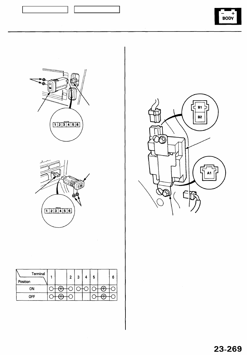
Switch Test
1. Remove the rear window defogger switch.
With navigation system:
REAR
WINDOW
DEFOGGER
SWITCH
6P CONNECTOR
BULBS
(0.84 W x 2)
Without navigation system:
REAR
WINDOW
DEFOGGER
SWITCH
6P CONNECTOR
BULBS
(0.84 W x 2)
2. Disconnect the 6P connector from the switch.
3. Check for continuity between the terminals in each
switch position according to the table.
Rear Window Defogger Coil Test
1. Open the trunk lid.
2. Remove the right side panel.
3. Disconnect the 1P and 2P connectors from the rear
window defogger coil.
Terminal side of
male terminals
REAR WINDOW
DEFOGGER
COIL
Terminal side of
male terminals
COMPONENT GROUND
4. Remove the rear window defogger coil.
5. Check for continuity between the A1 and B2
terminals. There should be continuity.
6. Check for continuity between the B2 terminal and
component ground. There should be continuity.
7. If there is no continuity, replace the coil.
Main Menu
Table of Contents
Rear Window Defogger
Function Test
CAUTION: Be careful not to scratch or damage the defog-
ger wires with the tester probe.
1. Check for voltage between the positive terminal and
body ground with the ignition switch and defogger
switch ON.
There should be battery voltage.
• If there is no voltage, check for:
faulty defogger relay,
faulty defogger switch.
faulty defogger coil.
an open in the YEL/BLU wire.
• If there is battery voltage, go to step 2.
NEGATIVE TERMINAL
POSITIVE TERMINAL
2. Check for continuity between the negative terminal
and body ground.
If there is no continuity, check for an open in the
defogger ground wire.
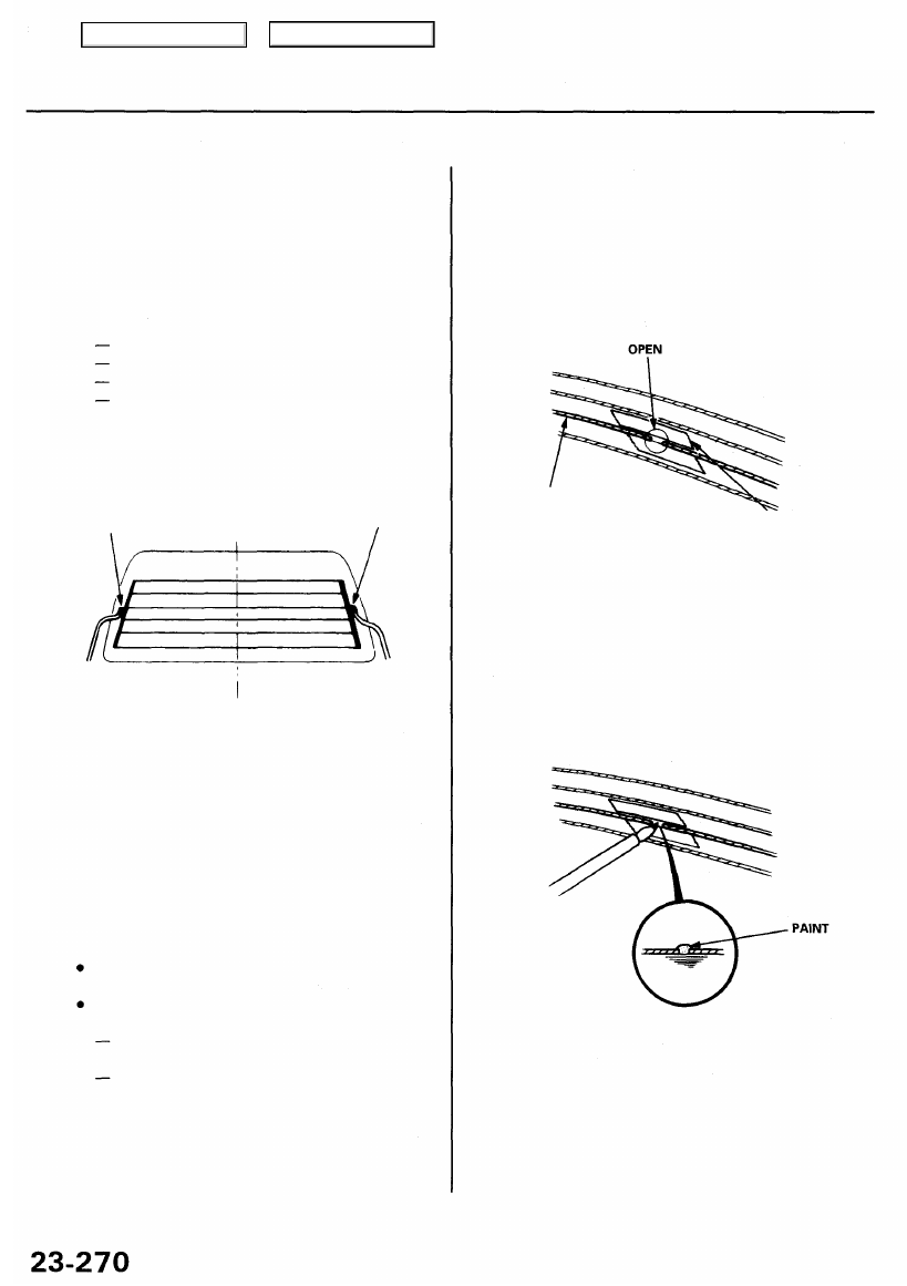
3. Touch the voltmeter positive probe to the halfway
point of each defogger wire, and the negative probe
to the negative terminal.
There should be about 6 V with the ignition switch
and the defogger switch ON.
If the voltage is as specified, the defogger wire is
OK.
If the voltage is not as specified, repair the
defogger wire.
If it is more than 6 V, there is a break in the
negative half of the wire.
If it is less than 6 V, there is a break in the
positive half of the wire.
Defogger Wire Repair
NOTE: To make an effective repair, the broken section
must be no longer than 1 inch.
1. Lightly rub the area around the broken section with
fine steel wool, then clean it with alcohol.
2. Carefully mask above and below the broken portion
of the defogger wire with cellophane tape.
3. Using a small brush, apply a heavy coat of silver
conductive paint extending about 1/8" on both
sides of the break. Allow 30 minutes to dry.
BROKEN WIRE
CELLOPHANE
TAPE
NOTE: Thoroughly mix the paint before use.
4. Check for continuity in the repaired wire.
5. Apply a second coat of paint in the same way. Let it
dry 3 hours before removing the tape.
Main Menu
Table of Contents
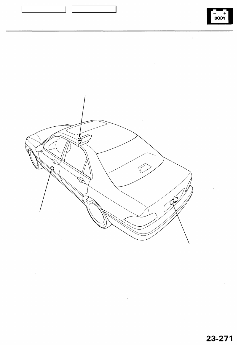
Trunk Lid Opener
Component Location Index
TRUNK LID OPENER MAIN SWITCH*
Test, page
TRUNK LID OPENER SWITCH*
Test, page
TRUNK LID OPENER SOLENOID
Test, page
*: You can also test the switch by using the self-diagnosis function (mode 2). (See page
.)
Main Menu
Table of Contents
Нет комментариевНе стесняйтесь поделиться с нами вашим ценным мнением.
Текст