Acura RL (1996-2004 year). Manual — part 415
Electronic Control System
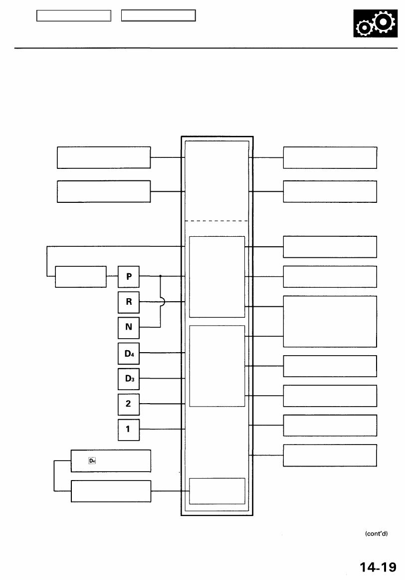
The electronic control system consists of a Powertrain Control Module (PCM), sensors, a A/T clutch pressure control
solenoid and four solenoid valves. Shifting and lock-up are electronically controlled for comfortable driving under all con-
ditions. The PCM is located below the dashboard, under the front lower panel on the passenger's side.
PCM
Throttle Position Sensor
Signal
Engine Coolant Temperature
Sensor Signal
Indicator Light
Self-Diagnosis Signal
PGM-FI
Control System
Shift Control
Lock-up Control
A/T Control System
Self-Diagnosis
Function
Vehicle Speed Sensor
Signal
Service Check Connector
Shift Solenoid
Valve A
Shift Solenoid
Valve B
A/T Clutch Pressure Control
Solenoid Valve
Torque Converter Clutch
(Lock-up Control)
Solenoid Valve A
Torque Converter Clutch
(Lock-up Control)
Solenoid Valve B
Mainshaft Speed Sensor
Signal
Countershaft Speed
Sensor Signal
Interlock System
Main Menu
Table of Contents
Description
Electronic Control System (cont'd)
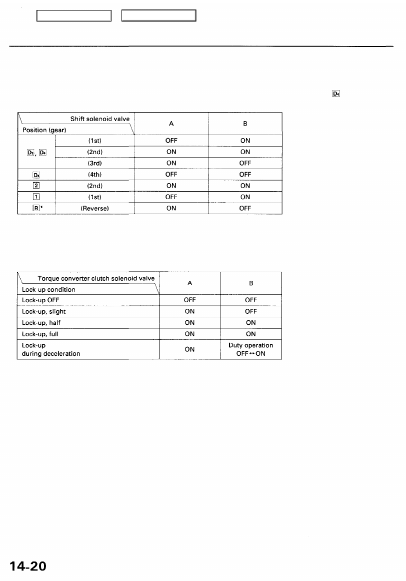
Shift Control
The PCM instantly determines which gear should be selected by various signals sent from sensors, and it actuates the
shift solenoid valves A and B to control shifting. Also, a Grade Logic Control System controls shifting in position while
the vehicle is ascending or descending a slope, or reducing speed.
for reverse inhibitor control description.
Lock-up Control
From sensor input signals, the PCM determines whether to turn the lock-up ON or OFF and activates torque converter
clutch (lock-up control) solenoid valve A and/or B accordingly. The combination of driving signals to torque converter
clutch (lock-up control) solenoid valves A and B is shown in the table below.
Main Menu
Table of Contents
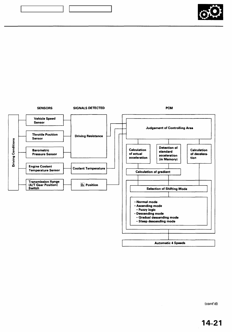
Grade Logic Control System
How it works:
The PCM compares actual driving conditions with driving conditions memorized in the PCM, based on the input from the
vehicle speed sensor, throttle position sensor, engine coolant temperature sensor, barometric pressure sensor, brake
pedal position switch signal and shift lever position signal, to control shifting while a vehicle is ascending or descending a
slope.
Main Menu
Table of Contents
Description
Electronic Control System (cont'd)
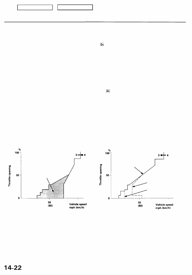
Ascending Control
When the PCM determines that the vehicle is climbing a hill in position, the system extends the engagement area of
3rd gear to prevent the transmission from frequently shifting between 3rd and 4th gears, so the vehicle can run smooth
and have more power when needed.
NOTE:
• Shift schedules between 3rd and 4th gear stored in the PCM enable the PCM's fuzzy logic to automatically select the
most suitable gear according to the magnitude of a gradient.
• Fuzzy logic is a form of artificial intelligence that lets computers respond to changing conditions much like a human
mind would.
Descending Control
When the PCM determines that the vehicle is going down a hill in position, the shift-up speed from 3rd to 4th gear
when the throttle is closed becomes faster than the set speed for flat road driving to widen the 3rd gear driving area.
This, in combination with engine braking from the deceleration lock-up, achieves smooth driving when the vehicle is
descending. There are two descending modes with different downshift (4-3) schedules according to the magnitude of a
gradient stored in the PCM. When the vehicle is in 4th gear, and you are decelerating on a gradual hill, or when you are
applying the brakes on a steep hill, the transmission will downshift to 3rd gear. When you accelerate, the transmission will
then return to 4th gear.
ASCENDING MODE
DESCENDING MODE
3RD/4TH SHIFTING
CHARACTERISTICS
CONTROL AREA
Flat road
mode
Steep descending
mode
Gradual descending
mode
Main Menu
Table of Contents
Нет комментариевНе стесняйтесь поделиться с нами вашим ценным мнением.
Текст