Acura RL (1996-2004 year). Manual — part 514
Troubleshooting
DTC 7-1: Right-front Solenoid (cont'd)
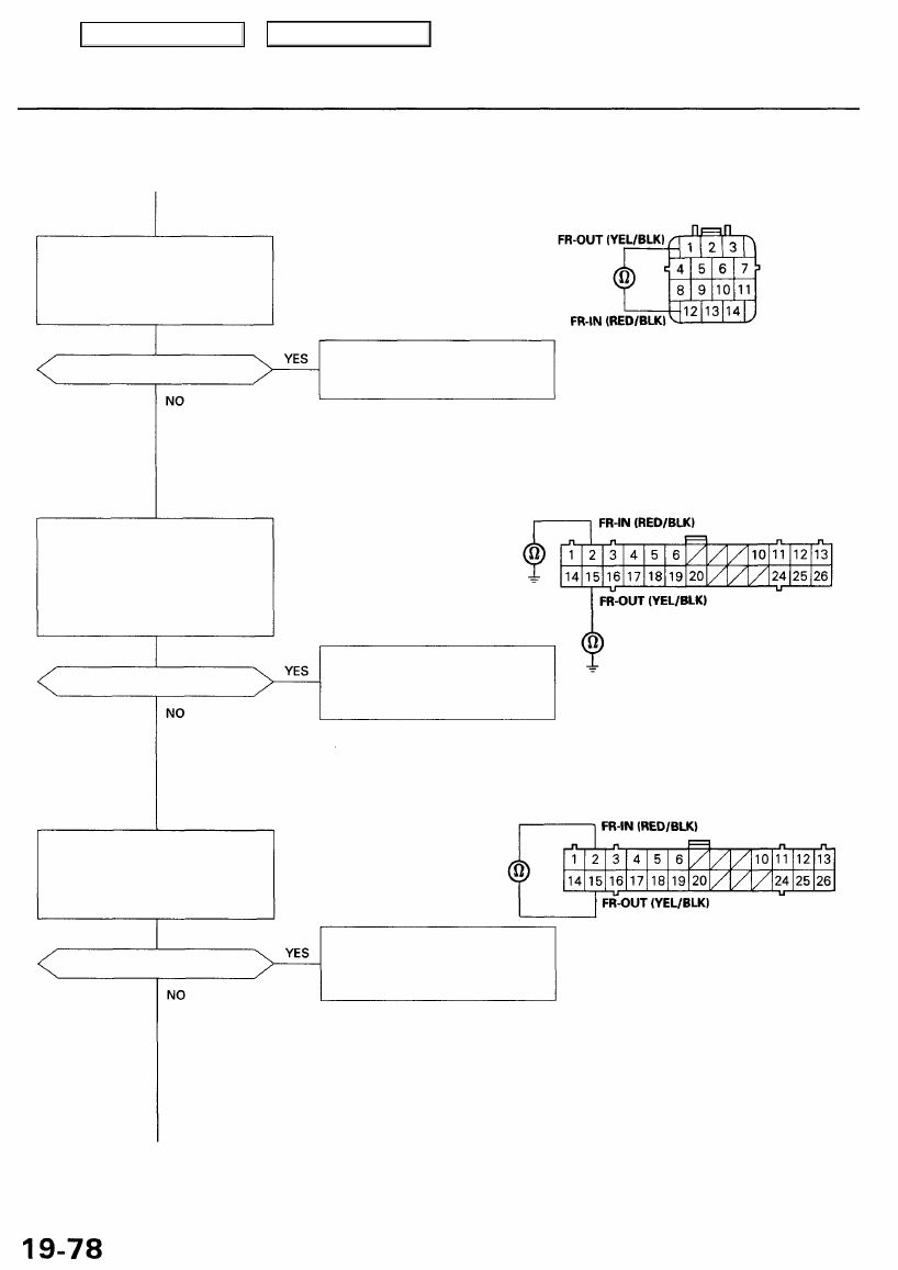
MODULATOR UNIT 14P CONNECTOR
Check for a short in the modula-
tor wire harness:
Check for continuity between the
modulator unit 14P connector ter-
minals No. 1 and No. 12.
Is there continuity?
Replace the modulator wire har-
ness. (Short to the FR-IN circuit
in the FR-OUT circuit.)
Wire side of female terminals
Check for a short to body ground
in the FR-IN and FR-OUT circuits:
1. Disconnect the ABS control
unit 26P connector.
2. Check for continuity between
body ground and terminals
No. 2 and No. 15 individually.
Is there continuity?
Repair short to body ground in
the FR-IN or FR-OUT circuit
between the ABS control unit
and modulator unit.
ABS CONTROL UNIT 26P CONNECTOR
Wire side of female terminals
Check for a short in the FR-IN
and FR-OUT circuits:
Check for continuity between the
ABS control unit 26P connector
terminals No. 2 and No. 15 .
Is there continuity?
Repair short to the FR-IN circuit
in the FR-OUT circuit between
the ABS control unit and modu-
lator unit.
Main Menu
Table of Contents
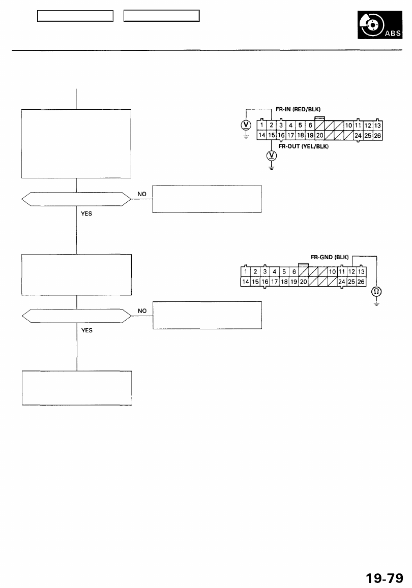
ABS CONTROL UNIT 26P CONNECTOR
Check for an open in the FR-IN
and FR-OUT circuits:
1. Connect the modulator unit
14P connector.
2. Measure the voltage between
body ground and the ABS con-
trol unit 26P connector termi-
nals No. 2 and No. 15 individu-
ally.
NOTE: Leave jumper wire
in fail-safe relay connector.
Wire side of female terminals
Is there battery voltage?
Repair open in the FR-IN or FR-
OUT circuit between the ABS
control unit and modulator unit.
Check for an open in the GND cir-
cuit:
Check for continuity between the
ABS control unit 26P connector
terminal No. 12 and body ground.
Is there continuity?
Repair open in the wire between
the ABS control unit and body
ground, or a poor ground (G402).
Check for loose ABS control unit
connectors. If necessary, substi-
tute a known-good ABS control
unit and recheck.
Main Menu
Table of Contents
Troubleshooting
DTC 7-2: Left-front Solenoid
During the initial diagnosis, after the fail-safe relays are turned on, and during the regular diagnosis, the ABS control unit
monitors the voltage from the battery for the six solenoids (when the ABS is not functioning). If the detection circuit for
the left-front solenoid detects 0 V, the ABS control unit keeps the ABS indicator light on after the engine is started. It turns
the ABS indicator light on again if it detects O V after the light goes off.
Possible causes:
Front fail-safe relay stuck OFF
Open circuit in the left-front solenoid drive circuits between the under-hood fuse/relay box and ABS control unit
Short circuit to body ground in the left-front solenoid drive circuits between the solenoids and ABS control unit
Faulty left-front solenoid drive transistor (ON) in the ABS control unit.
The ABS control unit momentarily outputs the ON signal to each solenoid (too momentary to turn the solenoid on) during
the initial diagnosis, and each time the vehicle is driven, to check the voltage from the battery with the detection circuit. If
the detection circuit for the left-front solenoids detects battery voltage at this time, the ABS control unit keeps the ABS
indicator light on. It turns the ABS indicator light on again if it detects the battery voltage when the vehicle is driven.
Possible causes:
Short circuit to power in the left-front solenoid drive circuits between the solenoids and ABS control unit
Faulty left-front solenoid drive transistor (OFF) in the ABS control unit
Short circuit to power in the left-front solenoid drive circuits in the modulator wire harness or solenoids
Short circuit to the left-front solenoid outlet circuit in the inlet circuit between the solenoids and ABS control unit
Short circuit to the right-front solenoid inlet or outlet circuit in the left-front solenoid inlet or outlet circuit between the
solenoids and ABS control unit
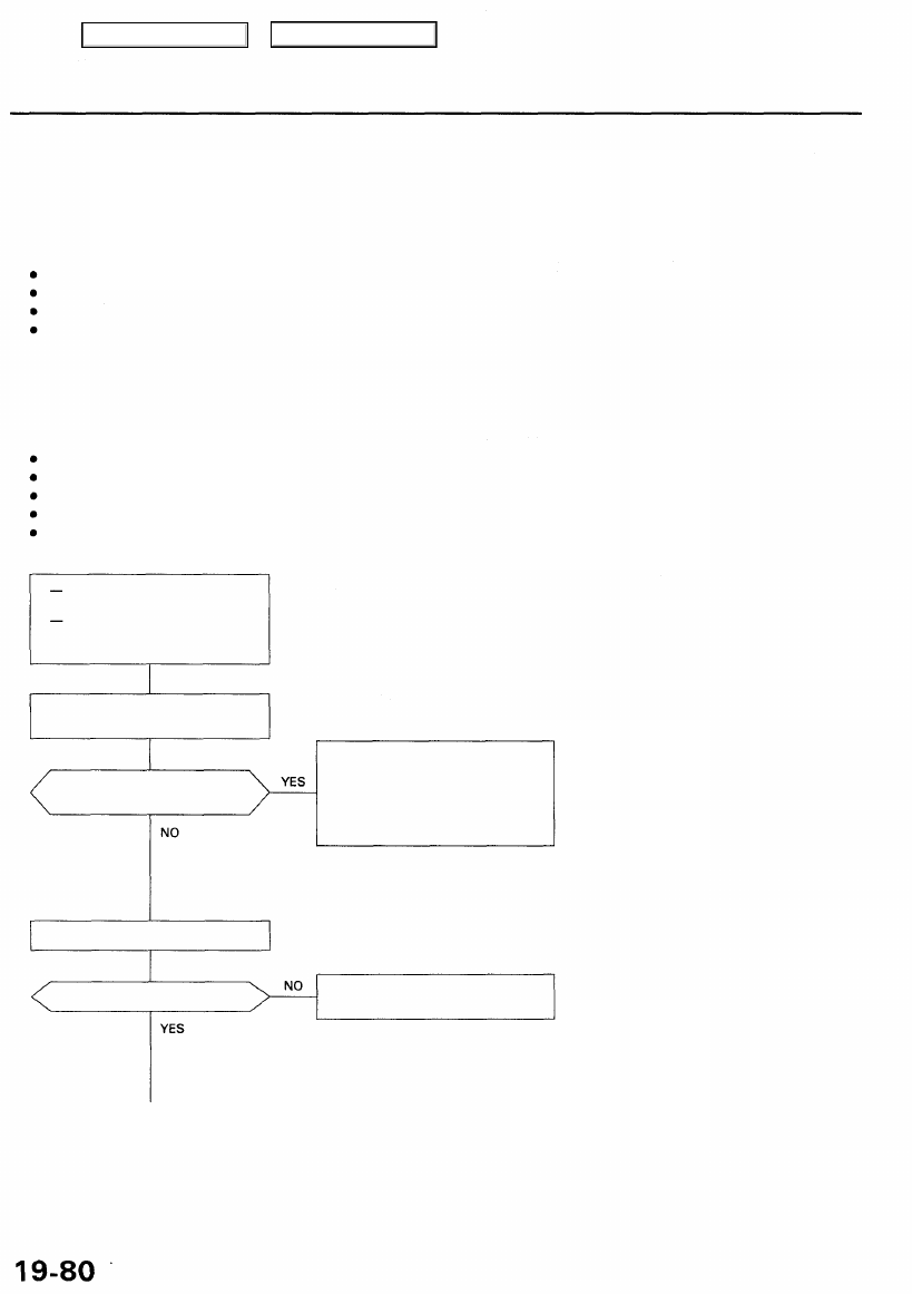
Does the ABS indicator light go
off?
The system is OK at this time.
Check the wire harness and con-
nectors between the ABS control
unit, fail-safe relay and modulator
unit (intermittent open or short
circuit).
Is code 7-2 indicated?
Perform the appropriate trouble-
shooting for the code.
Confirm the DTC that appears first.
Problem verification:
Start the engine.
With engine running, ABS indi-
cator light is ON.
With the SCS service connec-
tor connected (see page
Main Menu
Table of Contents
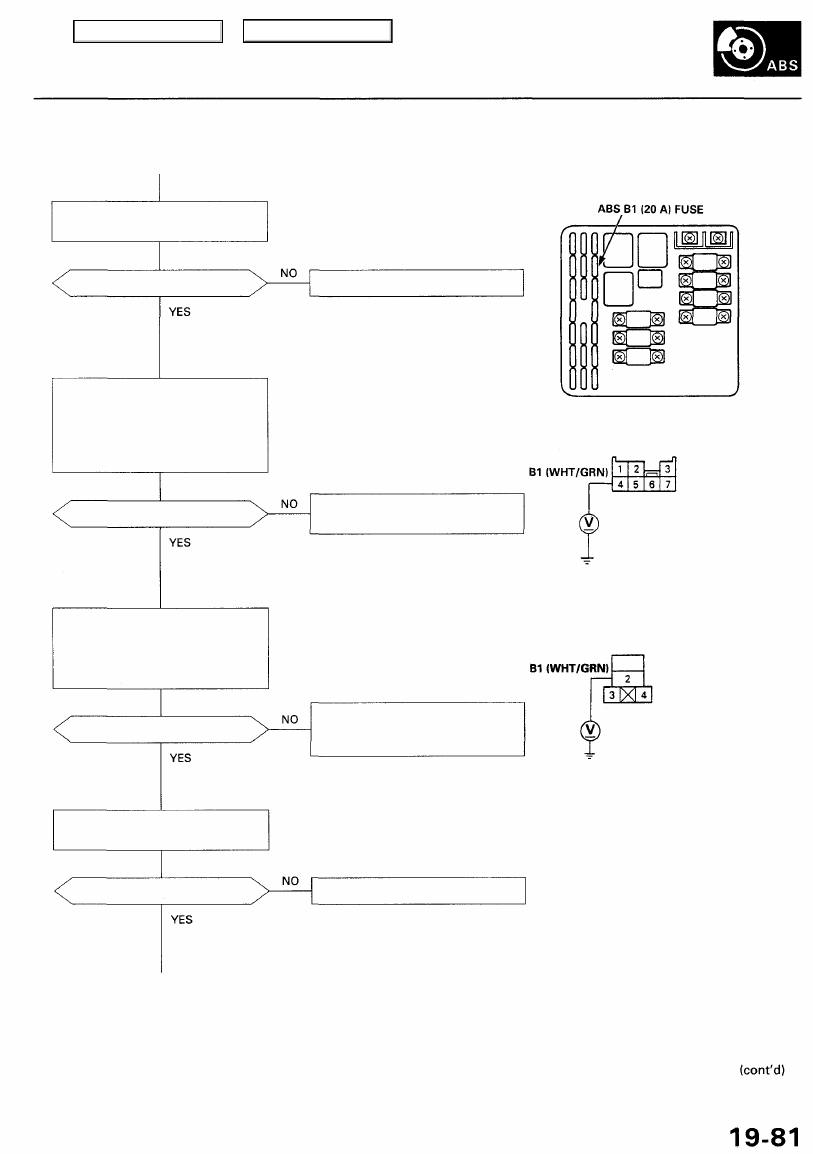
Is the fuse OK?
Check the under-hood ABS fuse/
relay box:
Measure the voltage between the
under-hood fuse/relay box 7P
connector terminal No. 4 and
body ground.
Is there battery voltage?
Check for an open in the B1 cir-
cuit:
1. Remove the front fail-safe relay.
2. Measure the voltage between
terminal No. 2 and body ground.
Is there battery voltage?
Is the relay OK?
UNDER-HOOD FUSE/RELAY BOX
Replace the fuse, and recheck.
NOTE: Reinstall the fuse if it is OK.
UNDER-HOOD FUSE/RELAY BOX
7P CONNECTOR
Repair open in the wire between
the under-hood fuse/relay box
and front fail-safe relay.
1
Terminal side of
female terminals
Replace the front fail-safe relay.
Check the front fail-safe relay (see
section 23).
FRONT FAIL-SAFE RELAY CONNECTOR
Replace the under-hood fuse/
relay box. (Internal open)
Wire side of female terminals
Check the ABS B1 (20 A) fuse in the
under-hood fuse/relay box.
Main Menu
Table of Contents
Нет комментариевНе стесняйтесь поделиться с нами вашим ценным мнением.
Текст