Acura RL (1996-2004 year). Manual — part 204
+
–
2004 American Honda Motor Co., Inc.
Connector Views
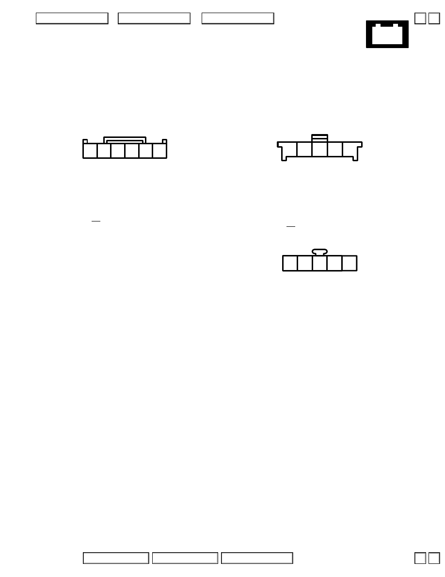
124. Hazard Warning Switch
– Center of dashboard
– On dashboard wire harness
’99-’03 Navigation:
– Gray (’99) or Green (’00-’03)
2 RED
3 GRN/WHT
4 WHT/GRN
5 BLK/RED
6
1
2
3
4
5
6
’04:
– Green
Navigation:
1 WHT/GRN
2 LT BLU
3 RED/BLK
4 RED
5
1
2
3
4
5
4
3
2
1
5
except Navigation:
1 RED/BLK
2 BLK/RED
3 WHT/GRN
4 GRN/WHT
5 RED
▲
▼
▲
▼
+
–
2004 American Honda Motor Co., Inc.
Connector Views
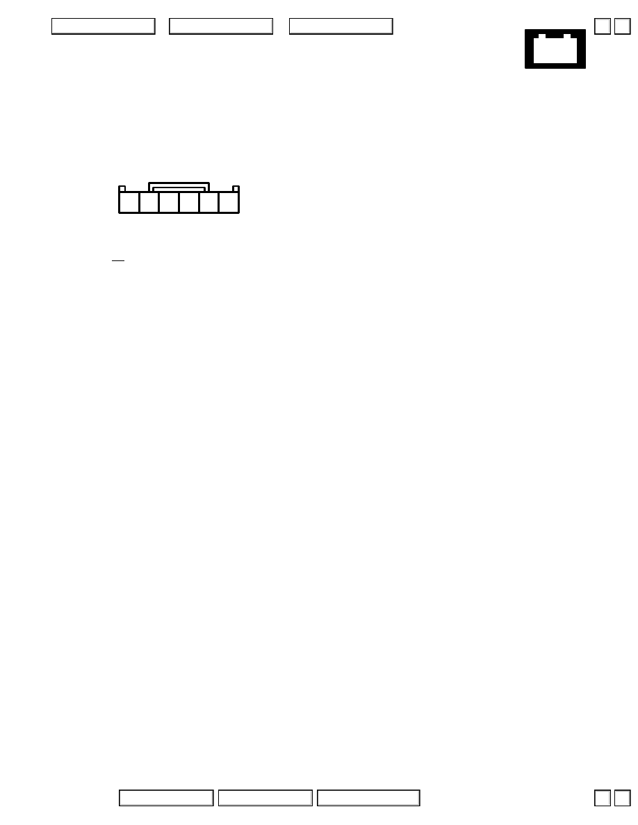
3 RED
4 BRN/YEL
(Front fog light relay control)
5 BLK
6 RED/BLU
1
2
3
4
5
6
125. Fog Light Switch (’99-’04 Navigation)
– Green (’99) or White (’00-’04)
– Center of dashboard
– On main wire harness
▲
▼
▲
▼
+
–
2004 American Honda Motor Co., Inc.
Connector Views
2
1
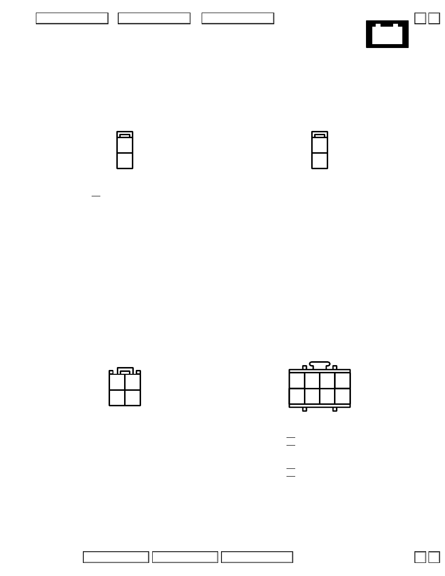
Connector B
– Yellow
3
4
1
2
126. Occupant Position Detection System (OPDS) Unit 4 (’99-’04)
– Left side of front passenger seat back
Connector A
– Yellow
2
1
Connector D
– Yellow
1
2
3 GRN
4 WHT/RED
5
6
7 BLU
8 BLK
1
2
3
4
5
6
7
8
Connector C
– Yellow
▲
▼
▲
▼
+
–
2004 American Honda Motor Co., Inc.
Connector Views
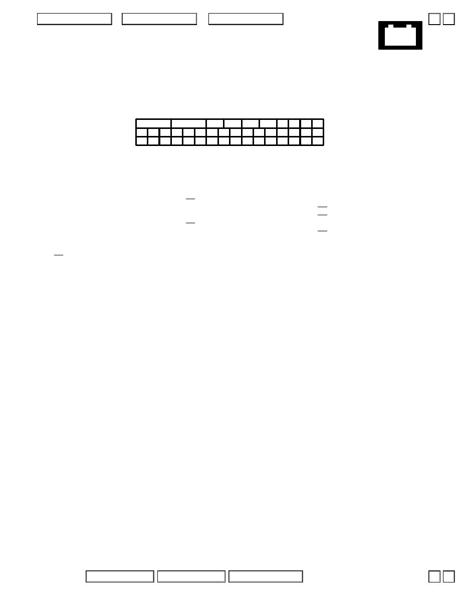
1 BLK
2 WHT/BLU
3 YEL
4 BLU
5 BLK
6 WHT/GRN
7 YEL/BLU
8 GRN
9 WHT
10 RED
11 LT GRN
12
13 BRN
14 LT BLU
15 GRN
16 GRN/BLK
17 BLU/WHT
18 GRY
19
20 RED
21 RED/BLU
22
23 YEL/BLK
24 WHT
25 YEL
26 BLU
27 WHT/BLK
28 GRN/BLU
29 GRY
30 BLU/YEL
31 GRN/YEL
32 GRN/WHT
33 LT GRN/RED
34
35
36 GRN/WHT
37
38 GRN/RED
39 YEL
40 PNK
41 BLK
42 GRN
12 13 14 15 16 17 18
11
19 20
3
7
21 22 23 24
8
9
25 26
10
28 29 30 31 32 33 34
27
35 36 37 38 39 40 41 42
1
2
4
5
6
127. VSA Modulator Control Unit (’00-’04)
– Black
– Right rear of engine compartment
– On main wire harness
▲
▼
▲
▼
Нет комментариевНе стесняйтесь поделиться с нами вашим ценным мнением.
Текст