Acura RL (1996-2004 year). Manual — part 220
205-3
2004 American Honda Motor Co., Inc.
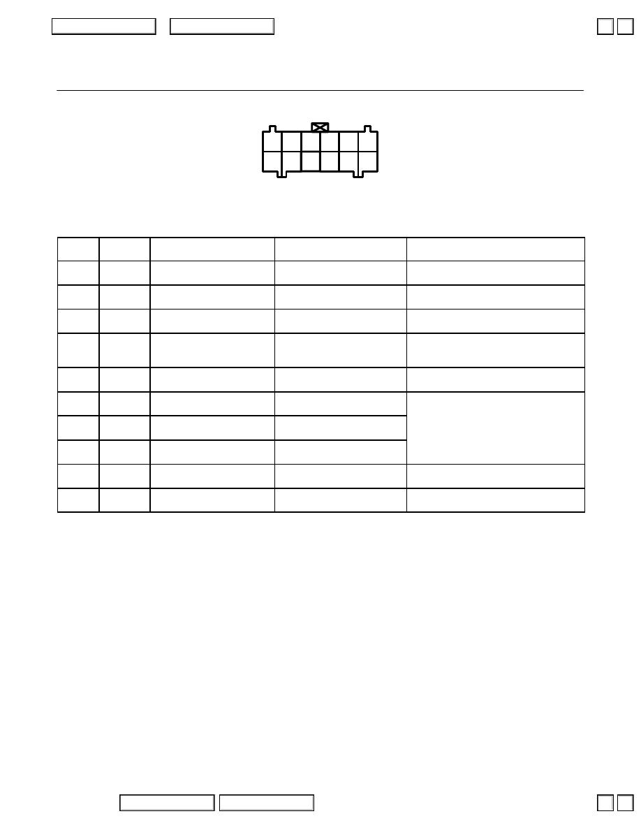
Engine/Powertrain Control Module Terminal Arrangement
wire side of female terminals
1
7
8
2
4
5
10
11
12
6
3
9
PCM Connector C (12P)
NOTE: Standard battery voltage is 12 V.
Terminal
number
Wire color
Terminal name
Description
Signal
2
PNK
ACS (A/C SWITCH SIGNAL)
Detects A/C switch signal.
With A/C switch ON: 0 V
With A/C switch OFF: approx. 10 V
3
GRN/RED
PDSW
(A/C PRESSURE SWITCH)
Detects A/C pressure switch
signal.
With A/C pressure switch ON: 0 V
With A/C pressure switch OFF: approx. 5 V
4
GRN
FLR2 (FUEL PUMP RELAY 2)
Drives fuel pump relay.
With engine at low rpm: battery voltage
With engine at high rpm: 0 V
5
RED
SCS
(SERVICE CHECK SIGNAL)
Detects service check connector
signal (the signal causing a DTC
indication)
With the connector connected: 0 V
With the connector disconnected: about 5 V
or battery voltage
6
BLU/RED
STS
(STARTER SWITCH SIGNAL)
Detects starter switch signal.
With starter switch ON: battery voltage
With starter switch OFF: 0 V
8
BLU
NEP
(ENGINE SPEED PULSE)
Outputs engine speed pulse.
With engine running: pulses
9*
LT GRN/
RED
TCINH (TRACTION
CONTROL INHIBIT)
FI
→
TCS, TCS operation
permission signal.
10*,*
1
BLK/ORN
TCFC (TRACTION CONTROL
FUEL CUT)
TCS (VSA)*
1
→
FI, fuel cut
(torque down) signal.
11
WHT
IMO CODE
(IMMOBILIZER CODE)
Detects immobilizer signal.
12*, *
1
PNK/BLK
TCSTB (TRACTION
CONTROL STANDBY)
TCS (VSA)*
1
→
FI, TCS (VSA)
operation start signal.
With TCS/VSA OFF: approx. 5 V
With TCS/VSA ON: 0 V
*: with TCS
*1: with VSA
▲
▼
▲
▼
205-4
2004 American Honda Motor Co., Inc.
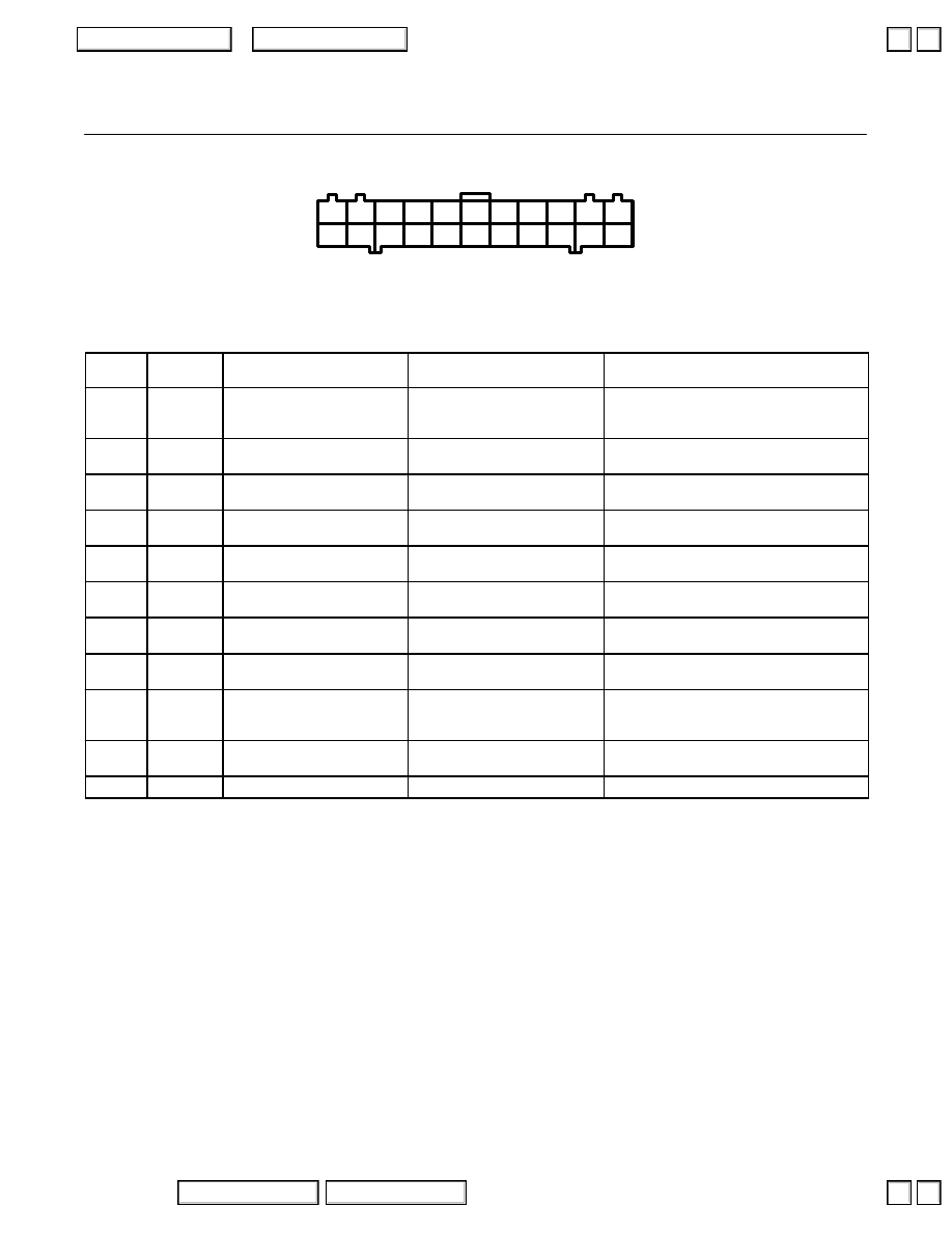
Engine/Powertrain Control Module Terminal Arrangement
wire side of female terminals
1
12
13
3
14
4
15
5
16
7
18
8
19
9
20
21
11
22
10
2
6
17
PCM Connector D (22P)
NOTE: Standard battery voltage is 12 V.
Terminal
number
Wire color
Terminal name
Description
Signal
1
WHT/YEL
VBU (VOLTAGE BACKUP)
Power source for the PCM
control circuit and the DTC
memory.
Battery voltage at all times
2
RED/BLU
KSR (RIGHT KNOCK
SENSOR (BANK 1))
Detects knock sensor signal.
With engine knocking: pulses
3*
GRN/ORN
BARO OUT (BAROMETRIC
SENSOR OUTPUT SIGNAL)
Sends barometric sensor output
signal.
With ignition switch ON (II): about 3 V
(depending on barometric pressure)
4
LT GRN
K-LINE
Sends and received OBD II scan
and PGM Tester signal.
With ignition switch ON (II): battery voltage
5
WHT/RED
ALTF
(ALTERNATOR FR SIGNAL)
Detects alternator FR signal.
With fully warmed up engine running: 0–5 V
(depending on electrical load)
6
RED/BLK
TPS (THROTTLE
POSITION SENSOR)
Detects TP sensor signal.
With throttle fully open: approx. 4.5 V
With throttle fully closed: about 0.5 V
7
RED/WHT
ECT (ENGINE COOLANT
TEMPERATURE SENSOR)
Detects ECT sensor signal.
With ignition switch ON (II): about 0.1–4.8 V
(depending on engine coolant temperature)
8
RED/YEL
IAT (INTAKE AIR
TEMPERATURE SENSOR)
Detects IAT sensor signal.
With ignition switch ON (II): about 0.1–4.8 V
(depending on intake air temperature)
9
RED/GRN
MAP (MANIFOLD ABSOLUTE
PRESSURE SENSOR)
Detects MAP sensor signal.
With ignition switch ON (II): about 3 V
At idle: about 1.0 V (depending on engine
speed)
10
YEL/RED
VCC1 (SENSOR VOLTAGE)
Power source for MAP sensor.
With ignition switch ON (II): about 5 V
With ignition switch OFF: 0 V
11
GRN/WHT
SG1 (SENSOR GROUND)
Ground for the MAP sensor.
*: with TCS
▲
▲
205-5
2004 American Honda Motor Co., Inc.
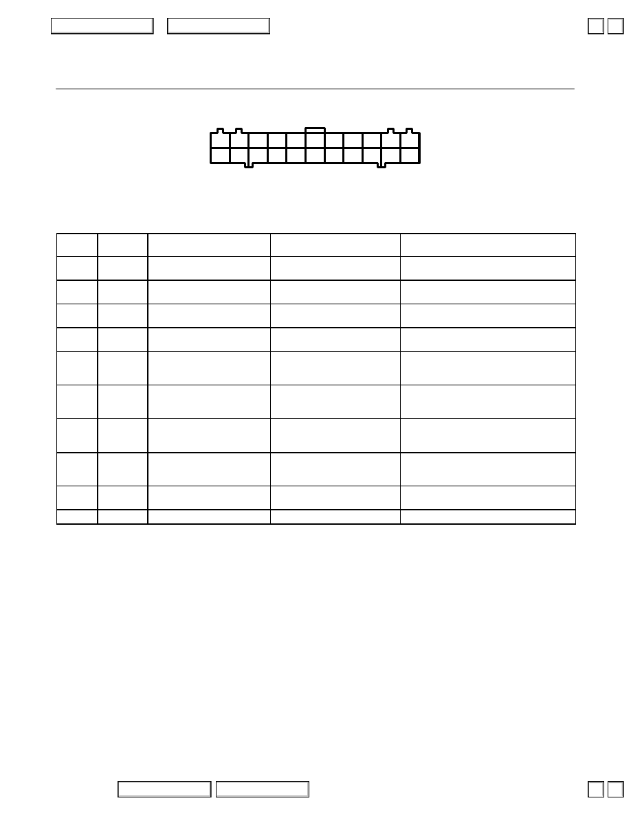
Engine/Powertrain Control Module Terminal Arrangement
wire side of female terminals
1
12
13
3
14
4
15
5
16
7
18
8
19
9
20
21
11
22
10
2
6
17
PCM Connector D (22P)
NOTE: Standard battery voltage is 12 V.
Terminal
number
Wire color
Terminal name
Description
Signal
12
BLK
CYP 1M
(CYP SENSOR 1M SIDE)
Ground for CYP sensor 1.
13
YEL
KSL (LEFT KNOCK SENSOR
(BANK 2))
Detects knock sensor signal.
With engine knocking: pulses
14
BLK/RED
CYP 2M
(CYP SENSOR 2M SIDE)
Ground for CYP sensor 2.
15
GRN/YEL
PTANK (FUEL TANK
PRESSURE SENSOR)
Detects fuel tank pressure
sensor.
With fuel fill cap opened: about 2.5 V
17
WHT/BLK
EGRL
(EGR VALVE LIFT SENSOR)
Detects EGR valve lift sensor
signal.
At idle without vacuum: about 1.2 V
With 27 kPa (200 mmHg, 8 in.Hg): about
4.3 V
18
BLU/RED
LPHO2S
(LEFT PRIMARY OXYGEN
SENSOR, SENSOR 1)
Detects primary oxygen sensor
(sensor 1) signal.
With throttle fully opened, fully warmed up
engine: above 0.6 V
With throttle quickly closed: below 0.4 V
19
WHT
RPHO2S
(RIGHT PRIMARY OXYGEN
SENSOR, SENSOR 1)
Detects primary oxygen sensor
(sensor 1) signal.
With throttle fully opened, fully warmed up
engine: above 0.6 V
With throttle quickly closed: below 0.4 V
20*
1
BLU/WHT
VREF
(REFERENCE VOLTAGE)
Provides reference voltage to
TCS control unit (VSA converter
unit)*
1
With ignition switch ON (II): about 5 V
With ignition switch OFF: 0 V
21
YEL/BLU
VCC2 (SENSOR VOLTAGE)
Provides sensor voltage.
With ignition switch ON (II): about 5 V
With ignition switch OFF: 0 V
22
GRN/BLK
SG2 (SENSOR GROUND)
Sensor ground.
*1: with VSA
▼
▼
205-6
2004 American Honda Motor Co., Inc.
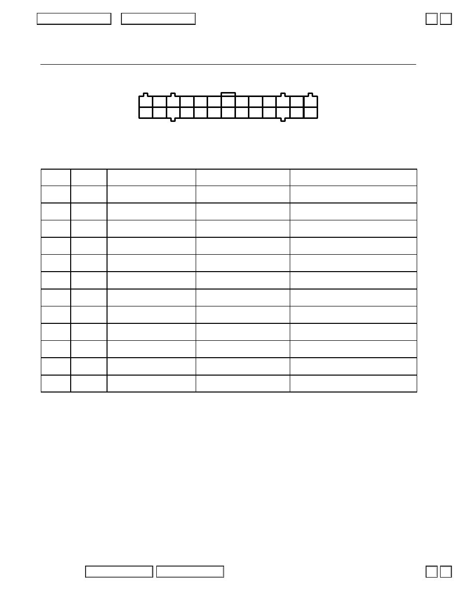
Engine/Powertrain Control Module Terminal Arrangement
wire side of female terminals
1
2
14
15
3
16
4
17
5
18
6
19
7
20
8
21
9
22
10
23
11
24
12
25
13
26
PCM Connector E (26P)
NOTE: Standard battery voltage is 12 V.
Terminal
number
Wire color
Terminal name
Description
Signal
1
BLK/YEL
VS SOL (BATTERY VOLTAGE
FOR SOLENOID VALVE)
Power source for solenoid
valves.
With ignition switch ON (II): battery voltage
With ignition switch OFF: 0 V
2
GRN/WHT
BKSW (BRAKE SWITCH)
Detects brake switch signal.
With brake pedal released: 0 V
With brake pedal depressed: battery voltage
3
RED
LS+ (LINEAR SOLENOID
VALVE +)
Drives linear solenoid valve.
With ignition switch ON (II): duty controlled
4
RED
NM (MAINSHAFT SPEED
SENSOR)
Detects mainshaft speed sensor
signal
With engine running: pulses
5
BLU
NC (COUNTERSHAFT
SPEED SENSOR)
Detects countershaft speed
sensor signal.
With ignition switch ON (II) and front wheels
turning: pulses
6*
PNK/BLU
TCSFT
(TCS SHIFT CONTROL)
Sends TCS shift control signal.
With engine running: pulses
7
WHT
ATPR (A/T GEAR
POSITION SWITCH)
Detects A/T gear position switch
signal.
In R position: 0 V
In any other position: battery voltage
8
YEL
ATPD4 (A/T GEAR
POSITION SWITCH)
Detects A/T gear position switch
signal.
In D
4
position: 0 V
In any other position: battery voltage
9
GRN
ATPD3 (A/T GEAR
POSITION SWITCH)
Detects A/T gear position switch
signal.
In D
3
position: 0 V
In any other position: battery voltage
10
BLU
ATP2 (A/T GEAR
POSITION SWITCH)
Detects A/T gear position switch
signal.
In 2 position: 0 V
In any other position: battery voltage
11
BRN
ATP1 (A/T GEAR
POSITION SWITCH)
Detects A/T gear position switch
signal.
In 1 position: 0 V
In any other position: battery voltage
12
BLU/YEL
SHA (SHIFT CONTROL
SOLENOID VALVE A)
Drives shift control solenoid
valve A
With engine running in 2, 3 : battery voltage
With engine running in 1, 4 : about 0 V
*: with TCS
▲
▲
Нет комментариевНе стесняйтесь поделиться с нами вашим ценным мнением.
Текст