Acura RL (1996-2004 year). Manual — part 495
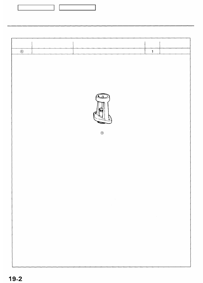
Special Tools
Ref. No.
Tool Number
Description
Qty
Page Reference
07JAG-SD40100 Pushrod Adjustment Gauge
Main Menu
Table of Contents
Component Locations
Index
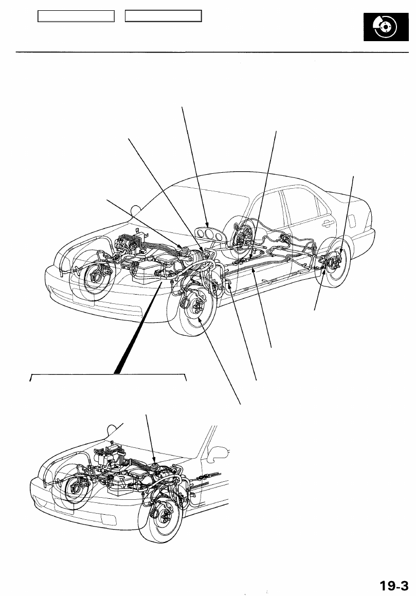
'96 - 99 models:
BRAKE SYSTEM INDICATOR
Parking Brake Pedal Switch Test, page
Brake Fluid Level Switch Test, page
BRAKE PEDAL
Inspection and Adjustment, page
PARKING BRAKE CABLE
Inspection and Replacement, page
MASTER CYLINDER/BRAKE BOOSTER
Bleeding, page
REAR BRAKES
Rear Brake Pads, page
Parking Brake Shoes Replacement, page
BRAKE HOSES/LINES
Inspection/Torque Specifications, page
PARKING BRAKE PEDAL
Inspection and Adjustment, page
FRONT BRAKES
Front Brake Pads, page
MASTER CYLINDER/BRAKE BOOSTER
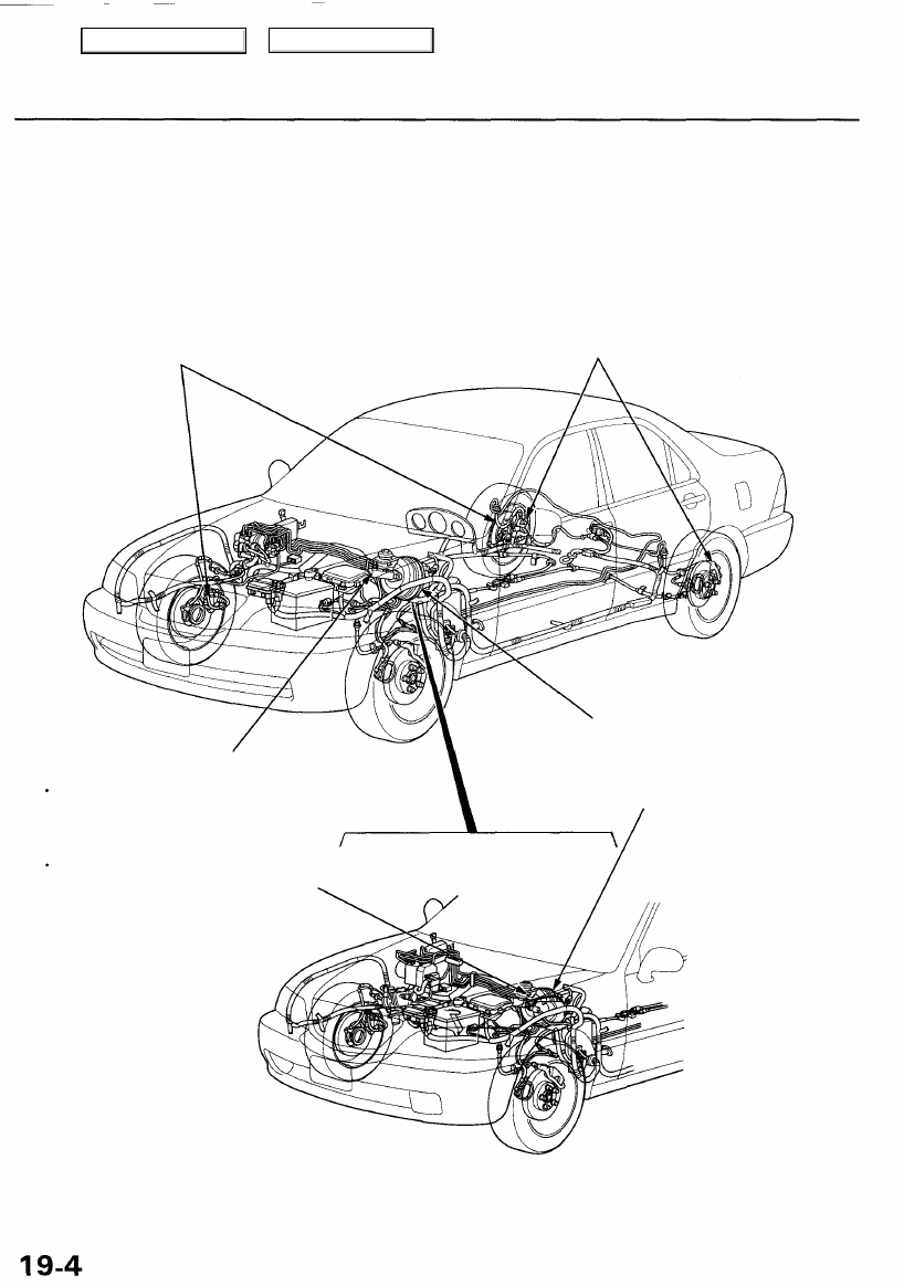
'00 - 01 models (USA):
Main Menu
Table of Contents
Inspection
'96-99 models:
Brake Hoses
Visually check for damage or signs
of fluid leakage. Replace the brake
hose with a new one if it is damaged
or leaking.
Caliper Piston Seal and Piston Boots
Check brake operation by applying the brake.
Visually check for damage or signs of fluid
leakage. If the pedal does not operate properly,
the brakes drag, or there is damage or signs of
fluid leakage, disassemble and inspect the
brake caliper. Replace the boots and seals with
new ones whenever the brake caliper is disassembled.
Master Cylinder Cup and Dust Seal
Check brake operation by applying the brakes.
Visually check for damage or signs of fluid
leakage. Replace the master cylinder as an
assembly if the pedal does not work properly
or if there is damage or signs of fluid leakage.
Check for a difference in brake pedal stroke
between quick and slow brake applications.
Replace the master cylinder if there is a
difference in pedal stroke.
Brake Booster
Check brake operation by applying the brakes.
If the brakes do not work properly, check the
brake booster. Replace the brake booster as an
assembly if it does not work properly or if there
are signs of leakage.
Brake System Rubber Parts and Brake Booster
'00 - 01 models (USA):
Main Menu
Table of Contents
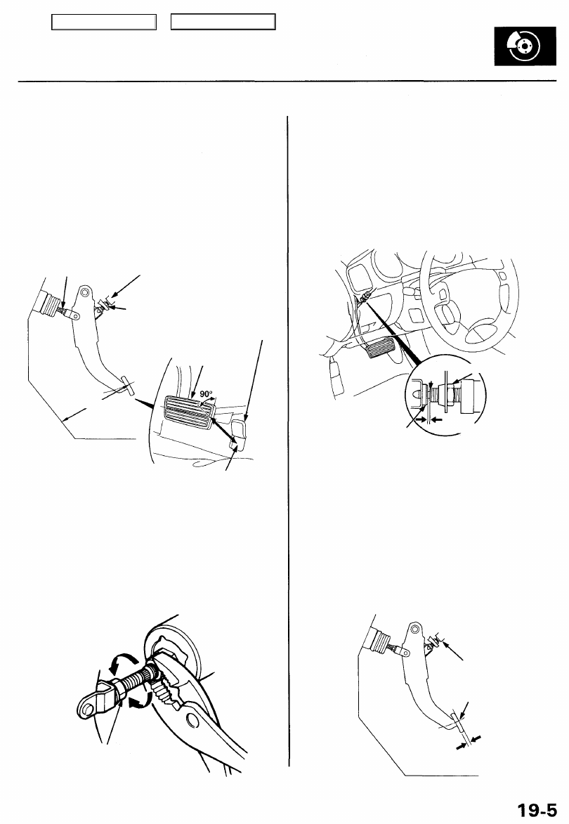
Inspection and Adjustment
Brake Pedal
Pedal Height
1. Disconnect the brake pedal position switch connec-
tor, loosen the brake pedal position switch locknut,
and back off the brake pedal position switch
until it is no longer touching the brake pedal.
2.
Lift up the carpet. At the insulator cutout, measure
the pedal height from the middle of the right side of
the pedal pad.
PUSHROD
LOCKNUT
BRAKE PEDAL POSITION SWITCH
BRAKE PEDAL POSITION SWITCH
LOCKNUT
INSULATOR
(CUTOUT)
MEASURING POINT
Standard Pedal Height (with carpet removed):
182 mm (7 3/16 in)
3. Loosen the pushrod locknut, and screw the pushrod
in or out with pliers until the standard pedal height
from the floor is reached. After adjustment, tighten
the locknut firmly.
NOTE: Do not adjust the pedal height with the
pushrod pressed.
Lower the pedal
PUSHROD LOCKNUT
15 N-m
(1.5 kgf-m, 11 Ibf-ft)
4.
Screw in the brake pedal position switch until its
plunger is fully pressed (threaded end touching the
pad on the pedal arm). Then back off the switch 1/4
turn to make 0.3 mm (0.01 in) of clearance between
the threaded end and pad. Tighten the locknut firm-
ly. Connect the brake pedal position switch connec-
tor.
CAUTION: Make sure the brake lights go off when
the pedal is released.
PAD
5. Check the brake pedal free play as described below.
Pedal Free Play
1. With the engine off, check the play on the pedal pad
by pushing the pedal by hand.
Free Play: 0.5 - 2.0 mm (0.02 - 0.08 in)
2. If the pedal free play is out of specification, adjust
the brake pedal position switch.
CAUTION: If the pedal free play is insufficient, it
may result in brake drag.
BRAKE PEDAL POSITION SWITCH
BRAKE PEDAL PAD
PEDAL FREE PLAY
LOCKNUT
THREADED
END
0.3 mm
(0.01 in)
BRAKE PEDAL PAD
PEDAL HEIGHT
Raise
the pedal
Main Menu
Table of Contents
Нет комментариевНе стесняйтесь поделиться с нами вашим ценным мнением.
Текст