Acura RL (1996-2004 year). Manual — part 627
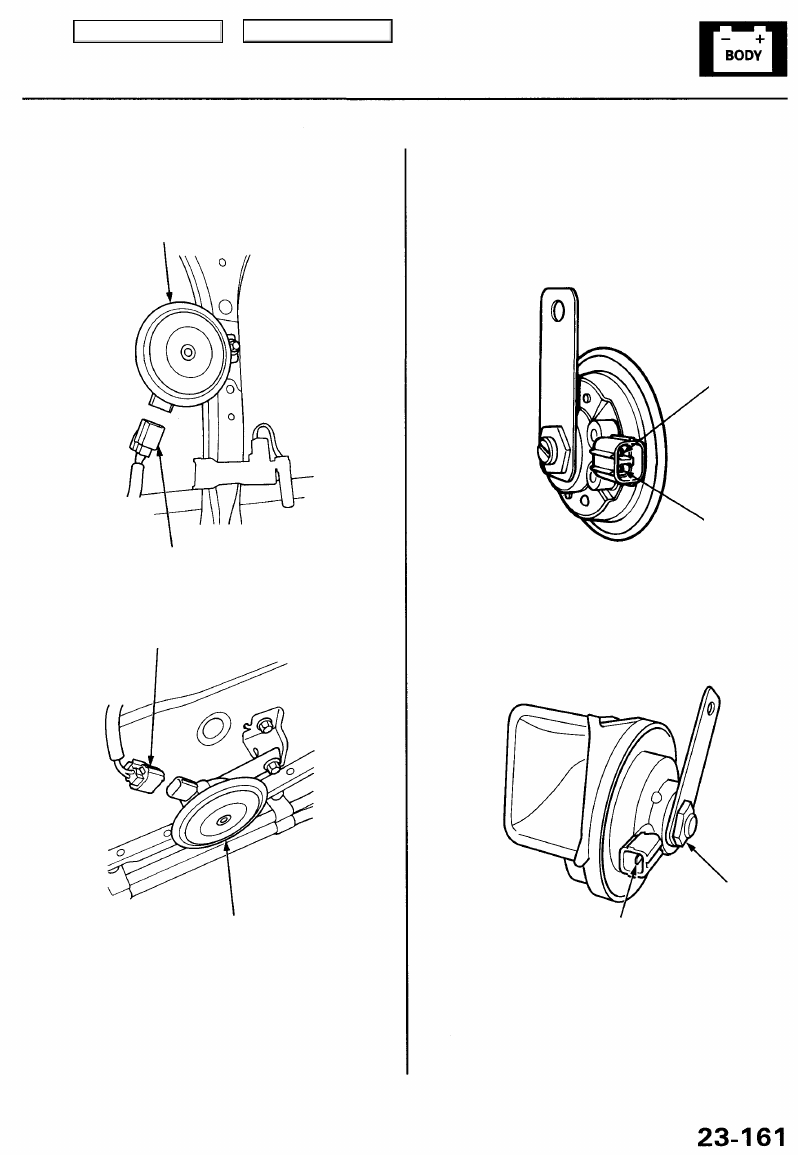
2. Remove the horns.
RIGHT HORN or SECURITY
HORN
CONNECTOR
CONNECTOR
Horn Test
1. Disconnect the 2P (or 1P) connectors from the
horns.
LEFT HORN
3. Test the horn by connecting battery power to one
terminal and grounding the other. The horn should
sound.
4. If the horn fails to work, replace it.
No. 2 (Ground)
No. 1
No. 1
No. 2
Main Menu
Table of Contents
• If there is continuity, the horn switch is OK.
• If there is no continuity, go to step 4.
Horns
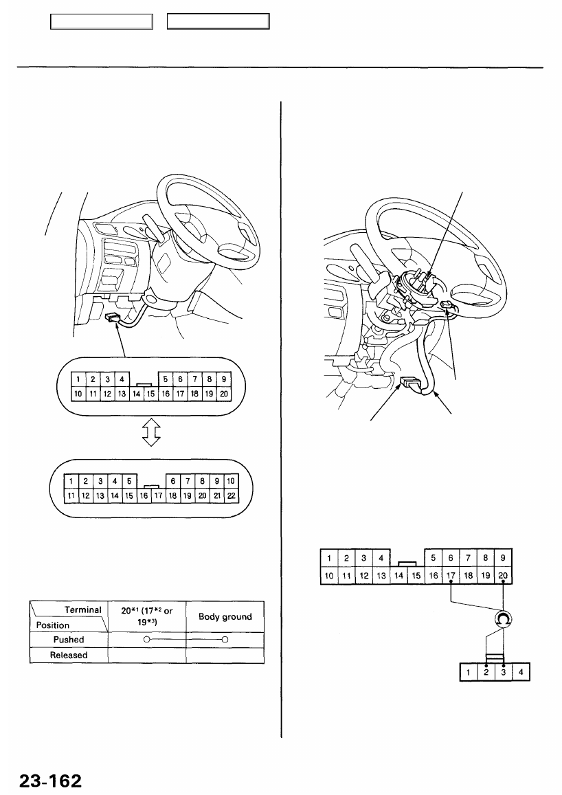
Switch Test
1. Remove the dashboard lower cover and knee
).
2. Disconnect the combination switch harness 20P
[22P] connector from the main wire harness.
[ ]: '00 - 01 Canada models
20P CONNECTOR
'96 - 99 models,
'00 USA model:
'00 - 01 Canada models:
22P CONNECTOR
Wire side of
female terminals
3. Check for continuity between the combination
switch harness 20P or 22P ('00 - 01 Canada models)
terminal and body ground in each horn switch
position.
*1: '96 -98 models
*2: '99 model and '00 - 01 USA models
*3: '00-01 Canada models
• If there is continuity, go to step 9.
• If there is no continuity, check for an open in the
wire of the combination switch harness.
Wire side of
female terminals
4P CONNECTOR
Wire side of female terminals
4. Remove the steering column upper and lower covers.
5. Disconnect the 4P connector from the cable reel.
6. Go to step 7 for except '00 - 01 Canada models, and
go to step 8 for '00 - 01 Canada models.
CABLE REEL
4P CONNECTOR
COMBINATION
SWITCH HARNESS
20P (or 22P) CONNECTOR
7. Check for continuity between the cable reel 4P con-
nector No. 3 terminal and 20P connector No. 20 ter-
minal ('96 - 98 models) or 4P connector No. 2 termi-
nal and 20P connector No. 17 terminal ('99 model
and '00 - 01 USA models) of the combination
switch harness.
20P CONNECTOR
Main Menu
Table of Contents
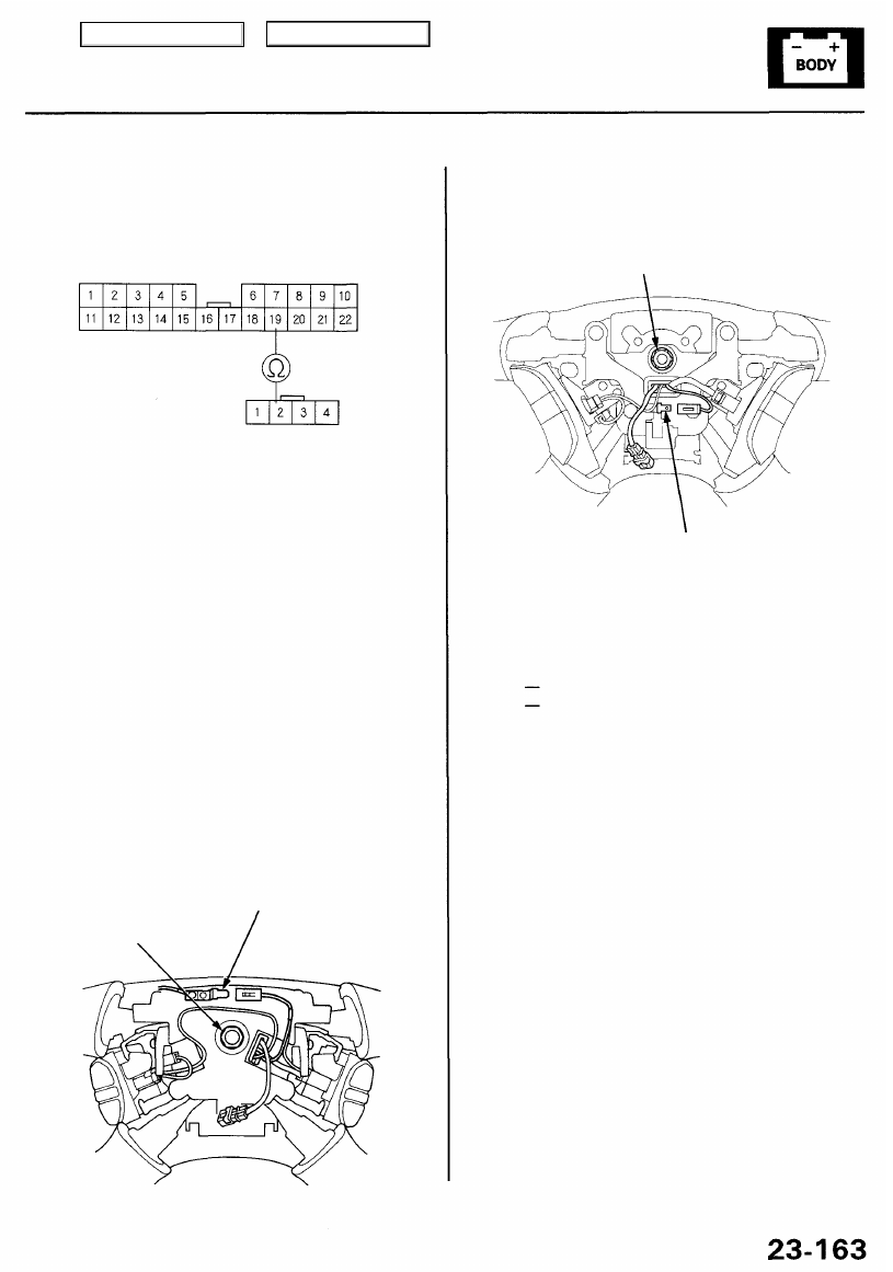
8. Check for continuity between the cable reel 4P
connector No. 2 terminal and combination switch
harness 22P connector No. 19 terminal.
22P CONNECTOR
4P CONNECTOR
Wire side of
female terminals
Wire side of
female terminals
• If there is continuity/ go to step 9.
• If there is no continuity, check for an open in the
wire of the combination switch harness.
9. Make sure you have the anti-theft code for the
radio, then write down the frequencies for the
radio's preset buttons.
10. Turn the ignition switch OFF.
11. Disconnect the battery negative cable, then
disconnect the positive cable, and wait at least 3
minutes.
12. Remove the driver's airbag (see
).
13. Check for continuity between the horn switch
positive terminal and steering wheel nut with the
horn switch pressed.
HORN SWITCH
POSITIVE TERMINAL
STEERING WHEEL
NUT
'96 - 98 models:
'99 - 00 models:
STEERING WHEEL NUT
HORN SWITCH
POSITIVE TERMINAL
• If there is continuity,
check the set/resume/cancel switch
• If there is no continuity, replace the horn switch.
14. If all the tests prove OK, reinstall and reconnect all
removed parts, then reconnect the battery cables.
15. Enter the anti-theft code for the radio, then enter the
customer's radio station presets.
16. Confirm proper system operation:
• Turn the ignition switch ON (II); the SRS
indicator light should come on for about 6
seconds and then go off.
• Make sure the horn button works.
Main Menu
Table of Contents
Seat Belt Tension Reducer
Test
NOTE: You can also test the switch by using the
selfdiagnosis function (mode 2). (See page
.)
1. Remove the center pillar lower trim (see
).
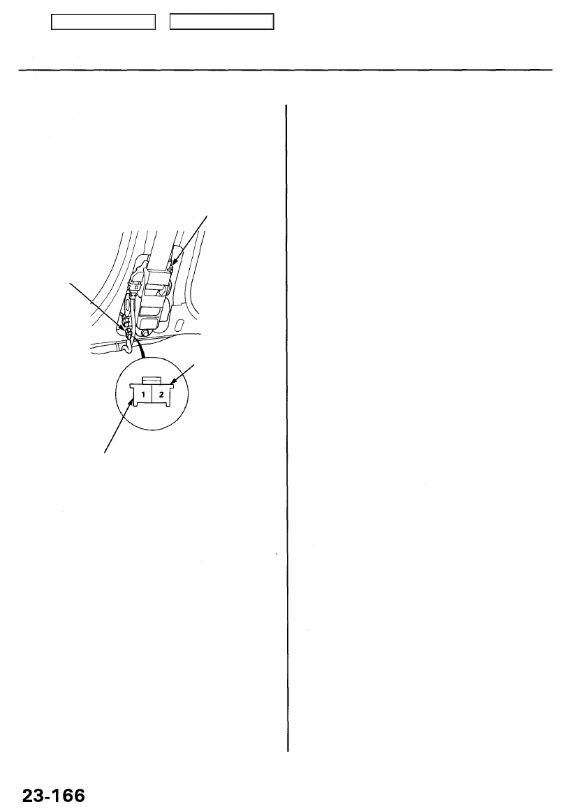
2. Disconnect the 2P connector from the seat belt
tensioner assembly.
SEAT BELT TENSIONER
ASSEMBLY
2P CONNECTOR
YEL
4. Turn the ignition switch OFF, and reconnect the 2P
connector to the seat belt tensioner assembly.
5. Check for voltage between the No. 1 terminal and
body ground with the ignition switch ON (II) and
seat belt unbuckled.
There should be battery voltage.
• If there is no voltage, replace the seat belt
tensioner assembly.
• If there is battery voltage, go to step 6.
6. Turn the ignition switch OFF.
7. Check for continuity between the No. 1 and body
ground with the seat belt buckled.
There should be continuity.
• If there is no continuity, check for:
— poor ground (G601, G651).
— an open in the BLU/RED wire.
— faulty seat belt switch.
3. Check for voltage between the No. 2 (+) terminal and
body ground with the ignition switch ON (II).
There should be battery voltage.
• If there is no voltage, check for:
— a blown No. 13 (7.5 A) fuse in the under-dash
fuse/relay box.
— an open in the YEL wire.
— faulty diode.
• If there is battery voltage, go to step 4.
BLU/RED: DRIVER'S and PASSENGER'S
('96 - 98 models)
BLU/WHT: PASSENGER'S ('99 - 01 models)
Wire side of
female terminals
Main Menu
Table of Contents
Нет комментариевНе стесняйтесь поделиться с нами вашим ценным мнением.
Текст