Acura RL (1996-2004 year). Manual — part 402
Emission Control System
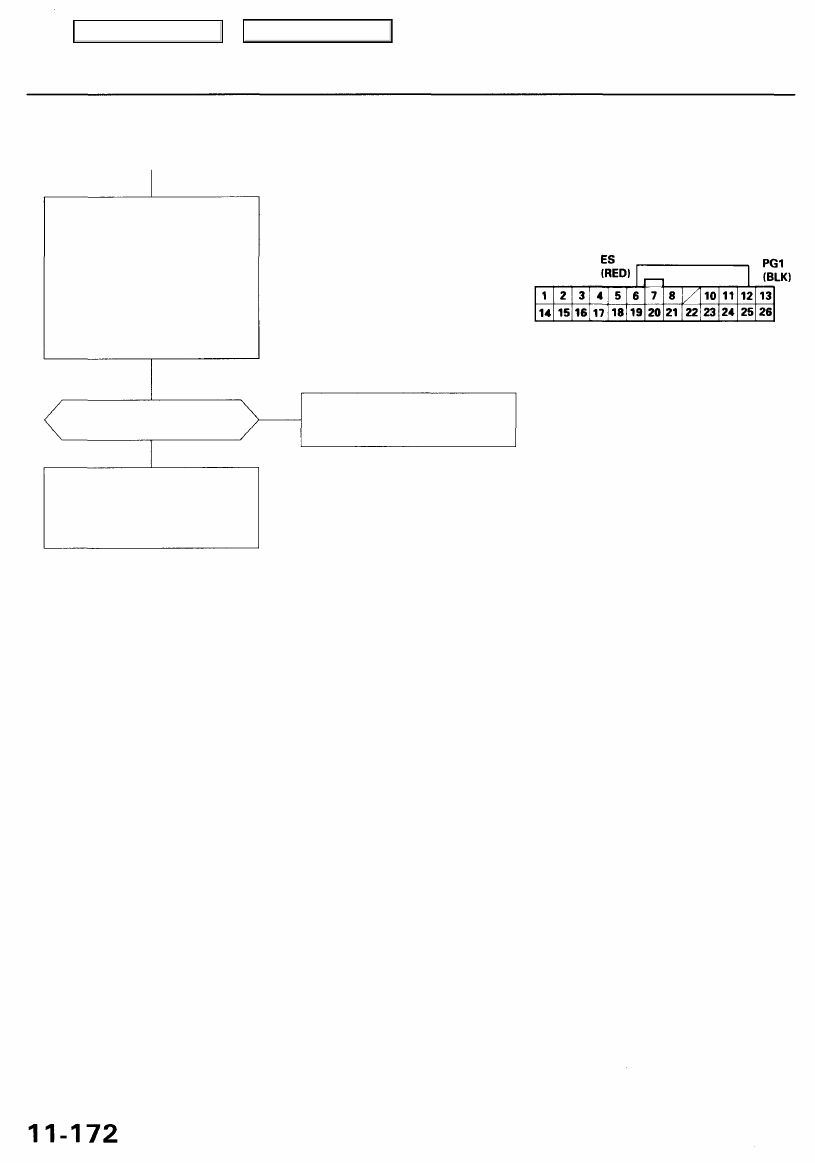
Exhaust Gas Recirculation (EGR) System (cont'd)
PCM CONNECTOR A (26P)
JUMPER WIRE
Wire side of female terminals
Does the engine stall or run
rough?
Repair open in the wire between
PCM (A6) and EGR valve vacuum
control solenoid valve.
YES
Substitute a known-good PCM
and recheck (see page
for
immobilizer information). If
symptom/indication goes away,
replace the original PCM.
Check for an open in the wire (ES
line):
1. Turn the ignition switch OFF
and reconnect the control box
connector.
2. Reconnect the No. 11 hose to
the EGR valve.
3. Start the engine and let it idle.
4. Connect PCM connector termi-
nals A6 and A12 with a jumper
wire.
NO
Main Menu
Table of Contents
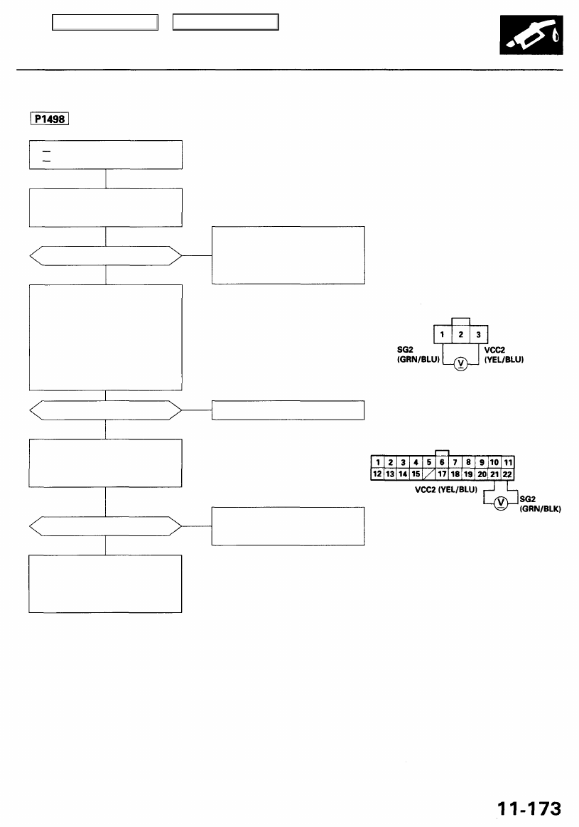
The scan tool indicates Diagnostic Trouble Code (DTC) P1498: A high voltage problem in the Exhaust Gas
Recirculation (EGR) valve position sensor circuit.
The MIL has been reported on.
DTC P1498 is stored.
Problem verification:
1. Do the PCM Reset Procedure.
2. Turn the ignition switch ON (II).
Is DTC P1498 indicated?
YES
Check for an open in the EGR
valve position sensor
1. Turn the ignition switch OFF.
2. Disconnect the EGR valve
position sensor connector.
3. Turn the ignition switch ON (II).
4. Measure voltage between the
EGR valve position sensor 3P
connector terminals No. 1 and
No. 2.
Is there approx. 5 V?
NO
Check for open in the wire (SG2
line):
Measure voltage between PCM
connector terminals D22 and D21.
Is there approx. 5 V?
NO
Substitute a known-good PCM
and recheck (see page
for
immobilizer information). If symp-
tom/indication goes away, replace
the original PCM.
Intermittent failure, system is OK
at this time. Check for poor con-
nections or loose wires at C251,
C254 (located at left shock tower),
C107 (EGR valve) and PCM.
EGR VALVE POSITION SENSOR CONNECTOR (C107)
Replace the EGR valve.
Wire side of female terminals
PCM CONNECTOR D (22P)
Repair open in the wire between
PCM (D22) and EGR valve posi-
tion sensor.
Wire side of female terminals
YES
YES
NO
Main Menu
Table of Contents
Emission Control System
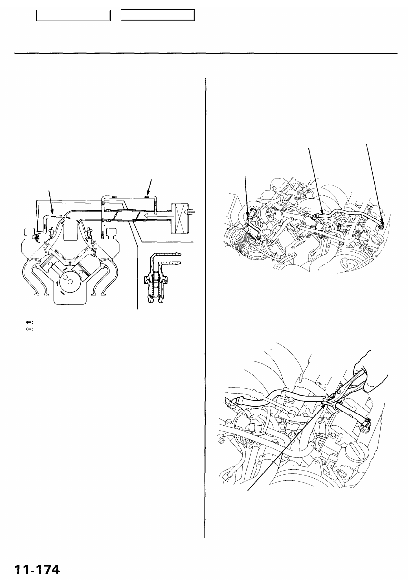
Positive Crankcase Ventilation (PCV) System
Description
The Positive Crankcase Ventilation (PCV) system is
designed to prevent blow-by gas from escaping to the
atmosphere. The PCV valve contains a spring-loaded
plunger. When the engine starts, the plunger in the PCV
valve is lifted in proportion to intake manifold vacuum and
the blow-by gas is drawn directly into the intake manifold.
BREATHER PIPE
PCV HOSE
PCV VALVE
BLOW-BY VAPOR
FRESH AIR
Inspection
1. Remove the engine cover. Check the PCV hoses and
connections for leaks and clogging.
PCV HOSE
PCV
VALVE
BREATHER
PIPE
2. At idle, make sure there is a clicking sound from the
PCV valve when the hose between the PCV valve
and intake manifold is lightly pinched with your fin-
gers or pliers.
Gently pinch here
If there is no clicking sound, check the PCV valve grom-
met for cracks and damage. If the grommet is OK,
replace the PCV valve and recheck.
Main Menu
Table of Contents
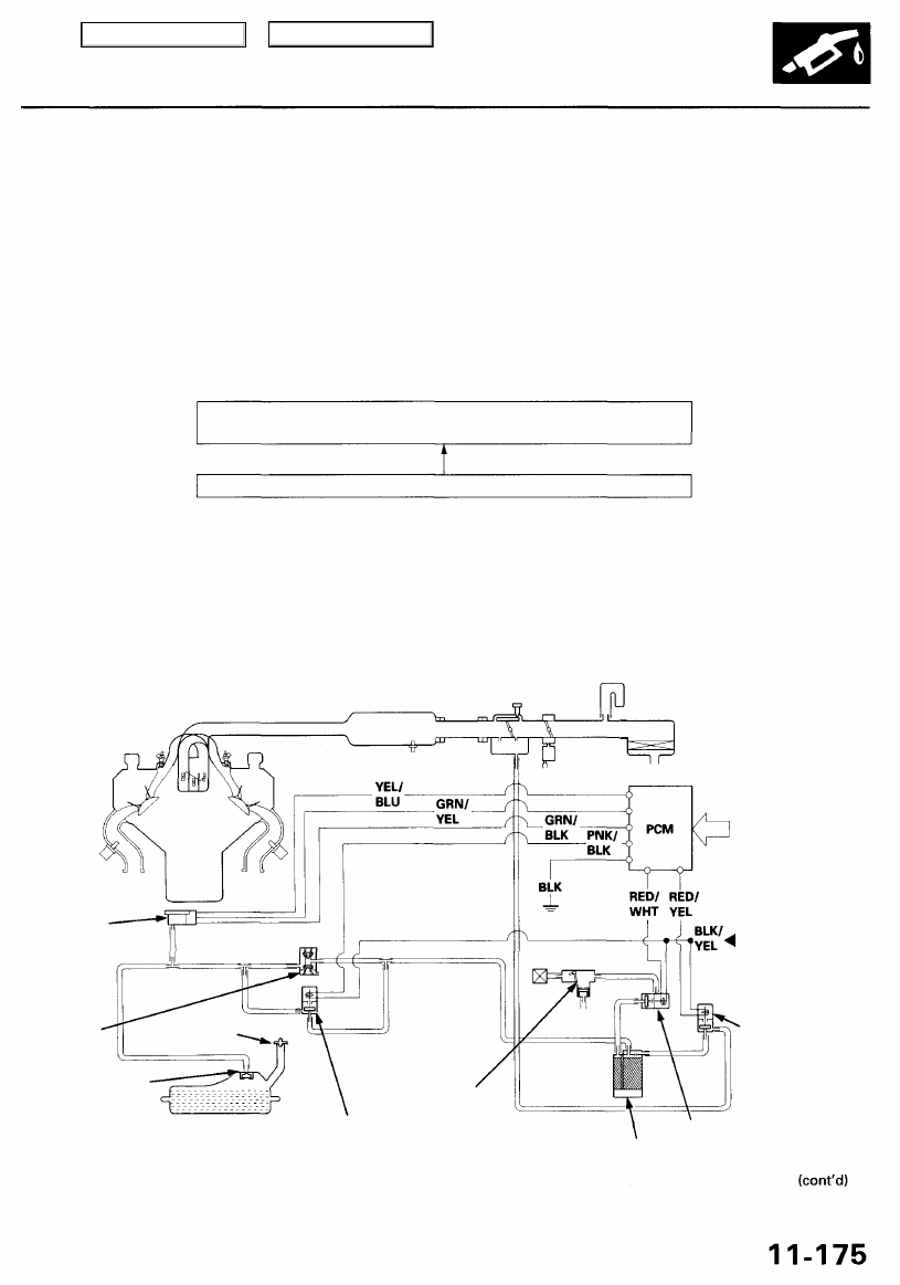
Evaporative Emission (EVAP) Controls
Description
The evaporative emission controls are designed to minimize the amount of fuel vapor escaping to the atmosphere. The
system consists of the following components:
A. Evaporative Emission (EVAP) Canister
An EVAP canister is used for the temporary storage of fuel vapor until the fuel vapor can be purged from the EVAP
canister into the engine and burned.
B. Vapor Purge Control System
EVAP canister purging is accomplished by drawing fresh air through the EVAP canister and into a port on the throttle
body. The purging vacuum is controlled by the EVAP canister purge valve.
EVAP CANISTER PURGE VALVE DUTY CONTROLLED AFTER START-
ING ENGINE
*: '96 - 99 models
*1: '00 - 01 models
C. Fuel Tank Vapor Control System
When fuel vapor pressure in the fuel tank is higher than the set value of the EVAP two way valve, the valve opens and
regulates the flow of fuel vapor to the EVAP canister.
During refueling, the fuel tank vapor control valve opens with the pressure in the fuel tank, and feeds the fuel vapor to
the EVAP canister.
'96 - 99 models:
FUEL
TANK
PRESSURE
SENSOR
EVAP
TWO WAY
VALVE
FUEL TANK
EVAP VALVE
FUEL TANK
EVAP CANISTER
PURGE VALVE
EVAP
BYPASS
SOLENOID
VALVE
EVAP
CANISTER
VENT SHUT VALVE
EVAP CONTROL
CANISTER
EVAP
THREE
WAY
VALVE
FUEL FILL
CAP
From
No. 20 ECU (PCM)
(20 A) FUSE
(in the under-dash
fuse/relay box)
VARIOUS
SENSORS
ENGINE COOLANT TEMPERATURE ABOVE 99°F (37°C)* 140°F (60°C)*
1
Main Menu
Table of Contents
Нет комментариевНе стесняйтесь поделиться с нами вашим ценным мнением.
Текст