Acura RL (1996-2004 year). Manual — part 425
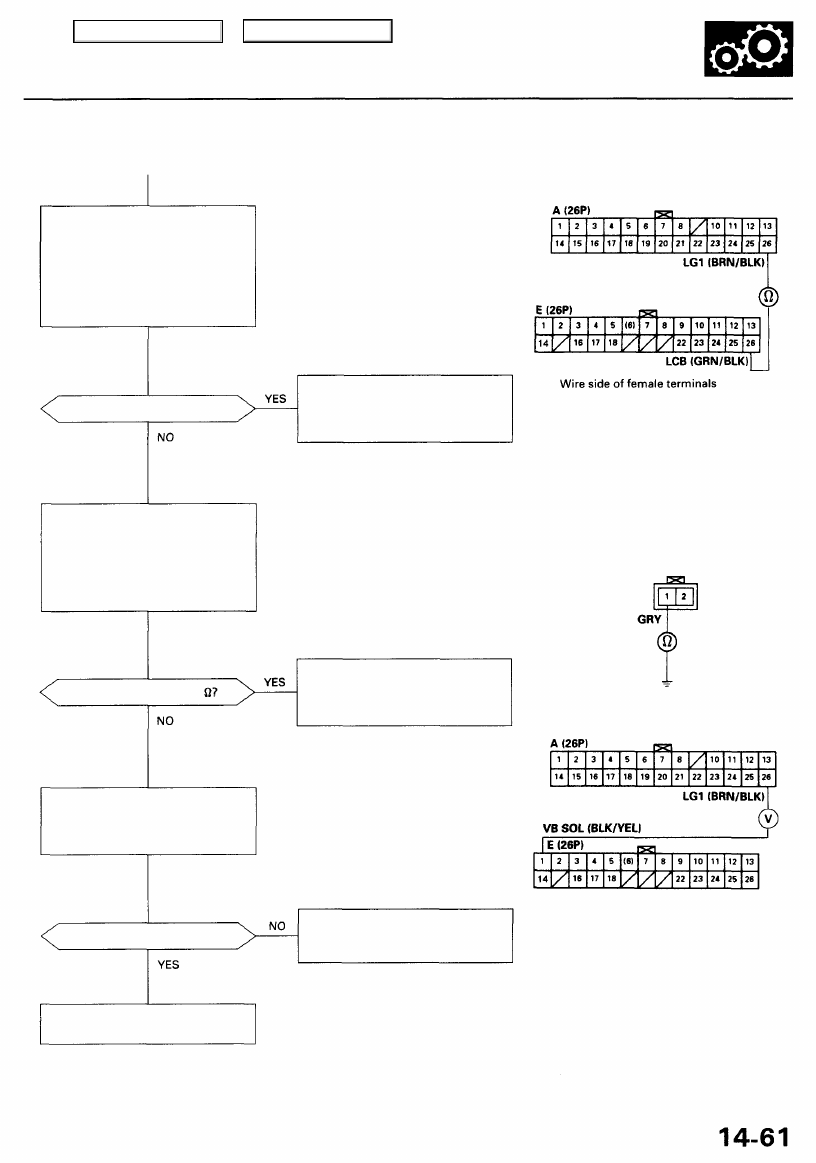
Check Torque Converter Clutch
Solenoid Valve B for a Short
Circuit:
1. Disconnect the 2P connector
from the torque converter
clutch solenoid valves A and B.
2. Check for continuity between
the E26 and A26 terminals.
Is there continuity?
Measure Torque Converter Clutch
Solenoid Valve B Resistance at the
Solenoid Connector
Measure the resistance between
the No. 1 terminal of the torque
converter clutch solenoid connec-
tor and body ground.
Is the resistance 12-25
Check the VB SOL Voltage:
1. Turn the ignition switch ON (II).
2. Measure the voltage between
the E1 and A26 terminals.
Is there voltage?
PCM CONNECTORS
Repair short to ground in the wire
between the E26 terminal and the
torque converter clutch solenoid
valve B.
Check for open in the wire
between the E26 terminal and the
torque converter clutch solenoid
valve B.
Check for open in the wire
between the E1 terminal and the
under-hood fuse/relay box.
TORQUE CONVERTER CLUTCH
SOLENOID VALVES A AND B
CONNECTOR
Terminal side of
male terminals
Replace the torque converter
clutch solenoid valves A and B.
Main Menu
Table of Contents
Electrical Troubleshooting
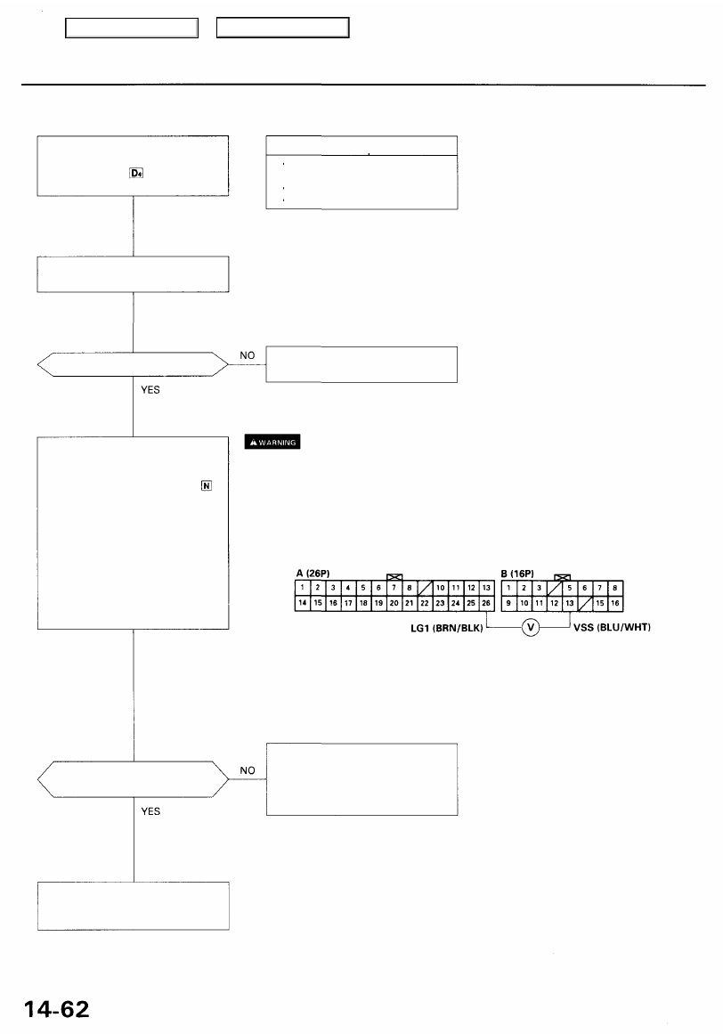
Troubleshooting Flowchart — Vehicle Speed Sensor (VSS)
• OBD II Scan Tool indicates Code
P1791.
• Self-diagnosis indicator light
blinks four times.
Possible Cause
• Disconnected vehicle speed
sensor (VSS) connector
• Short or open in VSS wire
• Faulty VSS
Check that the speedometer oper-
ates correctly.
Does the speedometer operate?
for vehicle
speed sensor (VSS) test.
Check the VSS Voltage:
1. Turn the ignition switch OFF.
2. Raise the vehicle.
3. Shift the transmission to
position.
4. Disconnect the A (26P) and B
(16P) c o n n e c t o r s from the
PCM.
5. Turn the ignition switch ON (II).
6. Rotate the front wheel and
check for the voltage between
the B13 and A26 terminals.
NOTE: Block the other wheel
so it does not turn or you will
get incorrect test results.
• Make sure lifts, jacks and safety stands are placed properly (see
).
• Set the parking brake securely, and block the rear wheels.
• Jack up the front of the vehicle, and support it with safety stands.
Does 0 V and approx. 5 V or more
appear alternately?
Check for open in the wire
between the B13 terminal and
the vehicle speed sensor (VSS). If
wire is OK, check the VSS (see
).
Check for loose PCM connectors.
If necessary, substitute a known-
good PCM and recheck.
PCM CONNECTORS
Wire side of female terminals
Main Menu
Table of Contents
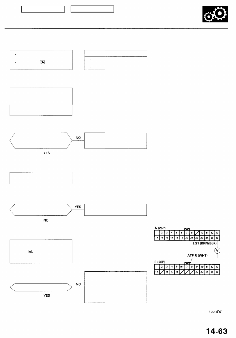
Troubleshooting Flowchart — Transmission Range (A/T Gear Position)
Switch (Short)
• OBD II Scan Tool indicates Code
P1705.
• Self-diagnosis indicator light
blinks five times.
Possible Cause
• Short in transmission range
switch wire
• Faulty transmission range switch
NOTE: Code P1705 (5) is caused when
the PCM receives two gear position
inputs at the same time.
Observe the A/T Gear Position
Indicator:
1. Turn the ignition switch ON (II).
2. Observe the A/T gear position
indicator, and shift each posi-
tion separately.
Does any indicator stay on
when the shift lever is not in
that position?
The system is OK at this time.
Check the wire harness for dam-
age.
Disconnect the transmission
range switch connector.
Do all gear position indica-
tors go out?
Replace the transmission range
switch.
PCM CONNECTORS
Measure ATP R Voltage:
1. Shift to all positions other
than
2. Measure the voltage between
the E7 and A26 terminals.
Is there approx. 10 V?
Check for short in the wire
between the E7 terminal and the
transmission range switch or A/T
gear position indicator. If wire is
OK, check for loose PCM connec-
tors. If necessary, substitute a
known-good PCM and recheck.
Wire side of female terminals
Main Menu
Table of Contents
Electrical Troubleshooting
Troubleshooting Flowchart — Transmission Range (A/T Gear Position)
Switch (Short) (cont'd)
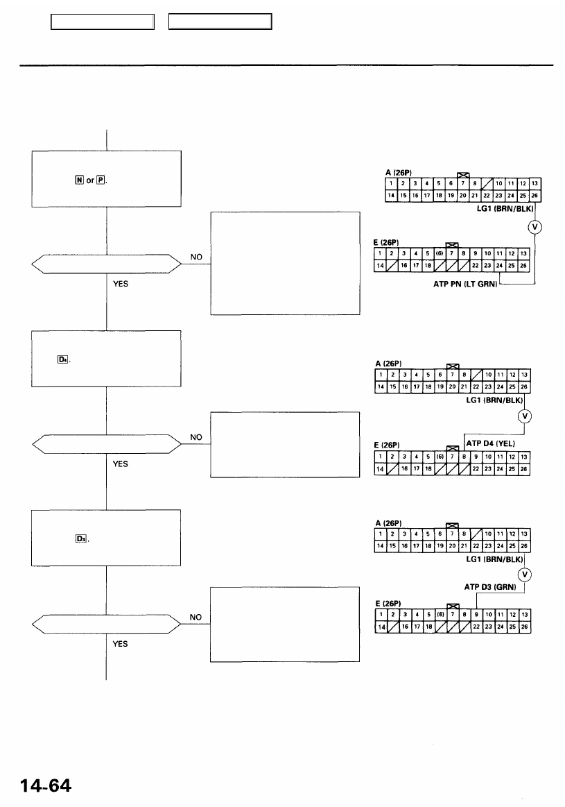
Is there approx. 10 V?
Measure ATP D4 Voltage:
1. Shift to all positions other than
2. Measure the voltage between
the E8 and A26 terminals.
Is there approx. 10 V?
Measure ATP 03 Voltage:
1. Shift to all positions other
than
2. Measure the voltage between
the E9 and A26 terminals.
Is there approx. 10 V?
Check for short in the wire
between the E24 terminal and the
A/T gear position indicator, or a
short in the wires between the
A/T gear position indicator and
the transmission range switch. If
wires are OK, check for loose PCM
connectors. If necessary, substi-
tute a known-good PCM and
recheck.
Check for short in the wire
between the E8 terminal and the
transmission range switch. If wire
is OK, check for loose PCM con-
nectors. If necessary, substitute
a known-good PCM and recheck.
Check for short in the wire
between the E9 terminal and the
transmission range switch or A/T
gear position indicator. If wire is
OK, check for loose PCM connec-
tors. If necessary, substitute a
known-good PCM and recheck.
PCM CONNECTORS
Wire side of female terminals
Measure ATP PN Voltage:
1. Shift to all positions other
than
2. Measure the voltage between
the E24 and A26 terminals.
Main Menu
Table of Contents
Нет комментариевНе стесняйтесь поделиться с нами вашим ценным мнением.
Текст