Acura RL (1996-2004 year). Manual — part 437
Pressure Testing
• While testing, be careful of the rotating front wheels.
• Make sure lifts, jacks and safety stands are placed properly (see
).
CAUTION:
• Before testing, be sure the transmission fluid is filled to the proper level.
• Warm up the engine before testing.
1. Raise the front of the vehicle, and support it with safety stands.
2. Set the parking brake, and block rear wheels securely.
3. Allow the front wheels to rotate freely.
4. Warm up the engine (the radiator fan comes on), then stop and connect a tachometer.
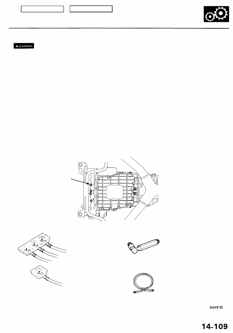
5. Connect the special tool to line pressure inspection hole.
TORQUE: 18 N-m (1.8 kgf-m, 13 Ibf-ft)
CAUTION: Connect the oil pressure gauge securely, be sure not to allow dust and other foreign particles to enter the
inspection hole.
LINE PRESSURE
INSPECTION HOLE
A/T OIL PRESSURE GAUGE
SET W/PANEL
A/T LOW PRESSURE
GAUGE W/PANEL
A/T PRESSURE HOSE
ADAPTER
(4 Required)
A/T PRESSURE HOSE,
2210 mm
(4 Required)
Main Menu
Table of Contents
Pressure Testing
(cont'd)
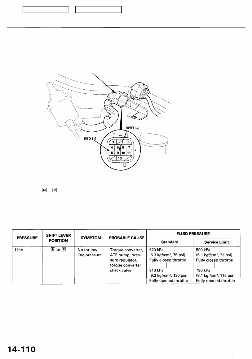
6. Disconnect the transmission sub-harness connector (14P).
7. Start the engine, and run it at 2,000 rpm.
Terminal side of female terminals
8. Shift to the or position, and measure line pressure at the fully opened throttle condition.
9. Connect battery voltage to the A/T clutch pressure control solenoid valve terminals of the transmission sub-harness
connector as shown.
10. Measure line pressure at the fully closed throttle condition.
If line pressure is out of specification, check and repair probable cause in the table below.
11. Stop the engine, and connect the transmission sub-harness connector (14P).
12. Disconnect the special tool from line pressure inspection hole, and connect the special tool to each inspection hole.
13. Start the engine, and run it as 2,000 rpm.
TRANSMISSION SUB-HARNESS
CONNECTOR (14P)
Main Menu
Table of Contents
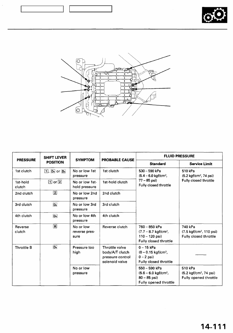
14. Shift to the respective shift lever position, and measure each clutch pressure.
4TH CLUTCH
PRESSURE
INSPECTION HOLE
3RD CLUTCH
PRESSURE
INSPECTION HOLE
THROTTLE B
PRESSURE
INSPECTION HOLE
1ST CLUTCH PRESSURE
INSPECTION HOLE
REVERSE CLUTCH PRESSURE
INSPECTION HOLE
1ST-HOLD CLUTCH PRESSURE
INSPECTION HOLE
2ND CLUTCH PRESSURE
INSPECTION HOLE
15. Disconnect the transmission sub-harness connector (14P), then measure throttle B pressure with the throttle fully opened.
16. Connect battery voltage to the A/T clutch pressure control solenoid valve terminals of the transmission sub-harness
connector as shown.
17. Measure throttle B pressure at the fully closed throttle condition.
18. Install the sealing bolts with new sealing washers in the inspection holes, and tighten the bolts to the specified torque.
TORQUE: 18 N-m (1.8 kgf-m, 13 Ibf-ft)
NOTE: Do not reuse old sealing washers.
LINE PRESSURE
INSPECTION HOLE
Main Menu
Table of Contents
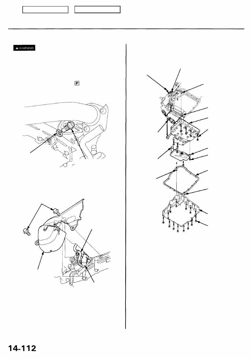
Lower Valve Body Assembly
Removal/Installation
Make sure lifts, jacks and safety stands are
).
1. Raise the front of the vehicle, and support it with
).
2. Set the parking brake, and block both rear wheels
securely.
3. Shift the transmission to the position.
4. Remove the drain plug, and drain the automatic
transmission fluid (ATP). Reinstall the drain plug
with a new sealing washer.
8. Remove the shift solenoid/A/T clutch pressure con-
trol solenoid valve harness connector stop.
6 x 1.0 mm
12 N-m (1.2 kgf-m,
8.7 Ibf-ft)
CONNECTOR STOP
O-RING
Replace.
O-RING
Replace.
DOWEL PIN
DOWEL PIN
DOWEL PIN
ATP PAN
6 x 1.0 mm
12 N-m (1.2 kgf-m,
8.7 Ibf-ft)
9. Remove the ATP pan (14 bolts).
10. Remove the ATP strainer (three bolts).
11. Remove the lower valve body assembly (six bolts)
while pushing the connector out of the transmission
housing.
12. Clean the inlet opening of the ATP strainer
thoroughly with compressed air, then check that it is
in good condition, and the inlet opening is not
clogged.
13. Replace the ATP strainer if it is clogged or dam-
aged.
NOTE: The ATP strainer can be reused if it is not
clogged.
14. Install the lower valve body assembly in the reverse
order of removal.
SEALING WASHER
Replace.
5. Remove the shift cable cover mounting bolts, then
remove the shift solenoid/A/T clutch pressure con-
trol solenoid valve harness clamp and connector
from the shift cable cover.
DRAIN PLUG
18 x 1.5 mm
49 N-m (5.0 kgf-m, 36 Ibf-ft)
DOWEL PIN
LOWER VALVE
BODY ASSEMBLY
6 x 1.0 mm
12 N-m (1.2 kgf-m,
8.7 Ibf-ft)
ATP STRAINER
6 x 1.0 mm
12 N-m (1.2 kgf-m,
8.7 Ibf-ft)
ATP PAN GASKET
Replace.
6 x 1.0 mm
12 N-m (1.2 kgf-m,
8.7 Ibf-ft)
SHIFT CABLE
COVER
SHIFT SOLENOID VALVE/
A/T CLUTCH PRESSURE
CONTROL SOLENOID VALVE
HARNESS CONNECTOR
CLAMP
6. Remove the shift cable cover from the transmission
housing.
7. Disconnect the shift solenoid/A/T clutch pressure
control solenoid valve harness connector.
Main Menu
Table of Contents
Нет комментариевНе стесняйтесь поделиться с нами вашим ценным мнением.
Текст