Acura RL (1996-2004 year). Manual — part 93
118
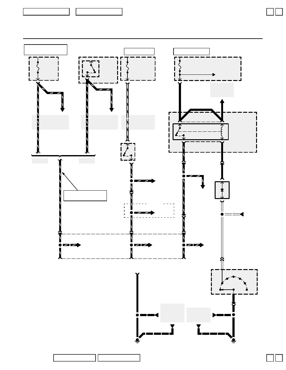
Trailer Lighting Connector
’96-’99
See Power
Distribution,
page 10-18.
See Headlight
Switch,
page 100-6.
See Ground
Distribution,
page 14-17
or 14-18.
BLK
BLK
C409
9
See A/T
Gear
Position
Indicator
STOP
HORN
15A
(20A
*
)
UNDER-
HOOD
FUSE/
RELAY
BOX
D4
N
R
P
D3
2
1
C470
2
C470
8
A/T GEAR
POSITION
SWITCH
BRAKE PEDAL
POSITION
SWITCH
Closed with
brake pedal
pressed.
3
WHT/YEL
5
C301
WHT/
YEL
METER
(
**
METER, SUN ROOF)
7.5A
See Power
Distribution,
page 10-10.
UNDER-
DASH
FUSE/
RELAY
BOX
2
C331
YEL
G701
TAIL-
LIGHT
RELAY
BLK
PNK
C306
4
RED/
YEL
9
TRAILER LIGHTING CONNECTOR
2
5
GRN/WHT
GRN/WHT
4
A/T
REVERSE
RELAY
1
C328
(
*
3)
5
)
3
)
(
*
5)
G402
PNK
2
WHT
GRN/BLK
GRN/BLK
SMALL
LIGHT
7.5A
UNDER-HOOD
RELAY BOX C
WHT
BLK
See Power
Distribution,
page 10-10.
YEL
YEL
1
2
8
C670
14
GRN/WHT
GRN/BLK
GRN/WHT
GRN/WHT
8
GRN/WHT
GRN/WHT
C413
A/T
REVERSE
DIODE
GRN/BLK
WHT
See Ground
Distribution,
page 14-12.
BLK
See
Navigation
System and
Automatic
Dimming
Mirror
GRN/BLK
GRN/BLK
C327
16
GRN/BLK
2
)
(
**
3)
*
= ’98-’04
**
= ’99-’04
UNDER-
HOOD
FUSE/
RELAY
BOX
UNDER-HOOD
FUSE/RELAY BOX C
RED/YEL
RED/
YEL
See Headlight
Switch,
page 100-9.
RED/BLK
RED/BLK
RED/BLK
3
16
RED/YEL
)
(
**
RED/BLK)
’96-’98
’99-’04
RED/YEL
)
(
**
RED/BLK)
RED/YEL
)
(
**
RED/BLK)
GRN/WHT
HOT AT ALL TIMES
HOT IN ON OR START
HOT WITH HEADLIGHT
SWITCH IN HEAD OR PARK
HOT WITH HEADLIGHT
SWITCH IN HEAD OR PARK
2004 American Honda Motor Co., Inc.
▲
▲
+
–
118-1
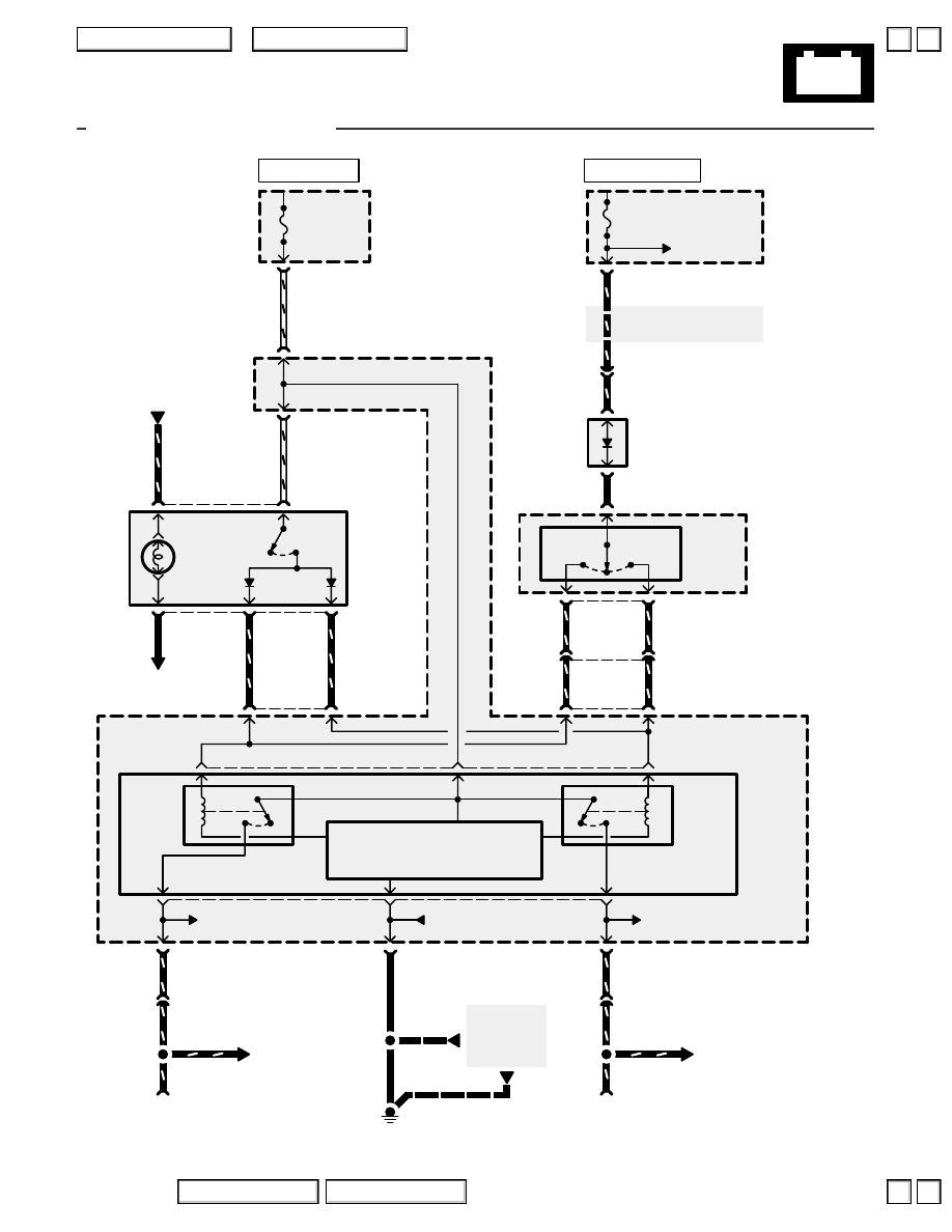
Trailer Lighting Connector
TRAILER LIGHTING
CONNECTOR
UNDER-HOOD
FUSE/RELAY
BOX
UNDER-DASH
FUSE/RELAY
BOX
UNDER-DASH
FUSE/RELAY
BOX
HAZARD
WARNING
SWITCH
COMBINATION
LIGHT
SWITCH
Turn
Signal
Switch
See Power
Distribution,
page 10-8.
TURN
SIGNAL/
HAZARD
RELAY
Right
Control
Left input/
control
Right
input/
control
Battery
input
Ground
Left
Control
Turn
Left
Turn
Right
Flasher
OFF
ON
C415
C403
C502
UNDER-
DASH
FUSE/
RELAY
BOX
C502
C331
C301
See Turn Signal and
Hazard Warning Lights
See Turn Signal and
Hazard Warning Lights
See Turn Signal
and Hazard
Warning Lights
C670
C651
C406
C405
See Ground Distribution,
page 14-4 or 14-8.
6
9
13
GRN/YEL
GRN/YEL
GRN/YEL
GRN/YEL
HAZARD
WARNING
SWITCH
LIGHT
C415
TRAILER LIGHTING
CONNECTOR
See Turn Signal
and Hazard
Warning Lights
C670
C651
1
10
17
PNK/BLU
PNK/BLU
PNK/BLU
PNK/BLU
4
2
6
4
G401 (’96-’98)
G251 (’99-’04)
See Ground
Distribution,
page 14-4
or 14-8.
BLK
BLK
RED/BLK
RED
1
(Navi 2)
5
)
GRN/WHT
BLK/RED
GRN/WHT
BLK/RED
See Power Distribution,
page 10-8.
TURN SIGNAL
SWITCH
DIODE
1
3
5
6
20
(
*
9)
8
)
(
*
8)
7
)
12
14
BLK/YEL
2
ECU
20A
13
BLK/YEL
RED
WHT/GRN
WHT/GRN
BLK/RED
(Navi 5)
2
)
GRN/WHT
(Navi 3)
4
)
4
20
HAZARD
10A
(Navi 4)
3
)
8
1
4
(
*
10)
9
)
BLK/YEL
*
= ’00-’01 Canada
1
2
Except ’04 Navigation
HOT IN ON OR START
HOT AT ALL TIMES
2004 American Honda Motor Co., Inc.
118-2
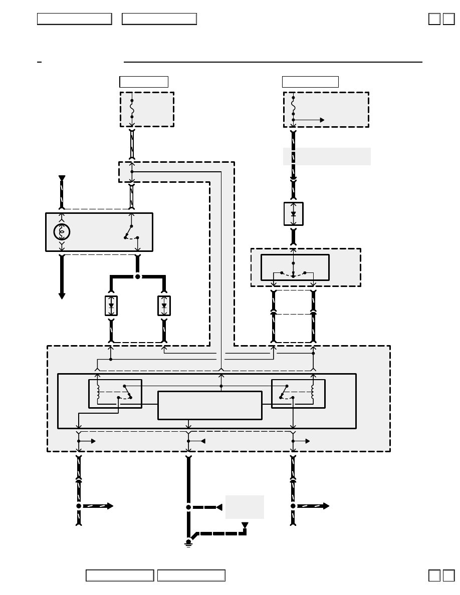
Trailer Lighting Connector
TRAILER
LIGHTING
CONNECTOR
UNDER-HOOD
FUSE/RELAY
BOX
UNDER-DASH
FUSE/RELAY
BOX
UNDER-DASH
FUSE/RELAY
BOX
COMBINATION
LIGHT
SWITCH
Turn
Signal
Switch
See Power
Distribution,
page 10-8.
TURN
SIGNAL/
HAZARD
RELAY
Right
Control
Left input/
control
Right
input/
control
Battery
input
Ground
Left
Control
Turn
Left
Turn
Right
Flasher
C415
C403
UNDER-
DASH
FUSE/
RELAY
BOX
C331
C301
See Turn Signal and
Hazard Warning Lights
See Turn Signal and
Hazard Warning Lights
See Turn Signal
and Hazard
Warning Lights
C670
C651
C406
C405
See Ground Distribution,
page 14-4.
6
9
13
GRN/YEL
GRN/YEL
GRN/YEL
GRN/YEL
C415
TRAILER
LIGHTING
CONNECTOR
See Turn Signal
and Hazard
Warning Lights
C670
C651
1
10
17
PNK/BLU
PNK/BLU
PNK/BLU
PNK/BLU
4
2
6
4
G251
See Ground
Distribution,
page 14-4.
BLK
BLK
GRN/WHT
BLK/RED
GRN/WHT
BLK/RED
See Power Distribution,
page 10-8.
TURN SIGNAL
SWITCH
DIODE
1
3
5
6
20
8
7
12
14
BLK/YEL
2
ECU
20A
13
BLK/YEL
RED
WHT/GRN
HAZARD
10A
1
4
9
)
BLK/YEL
1
2
’04 Navigation
4
HAZARD
WARNING
SWITCH
LT BLU
2
RED
20
4
C502
8
1
C502
WHT/GRN
RED/
BLK
3
OFF
ON
HAZARD
WARNING
SWITCH
LIGHT
HAZARD
WARNING
LIGHTS
DIODE 2
1
2
HAZARD
WARNING
LIGHTS
DIODE 1
1
2
GRN/WHT
BLK/RED
LT BLU
LT BLU
HOT IN ON OR START
HOT AT ALL TIMES
2004 American Honda Motor Co., Inc.
▼
▼
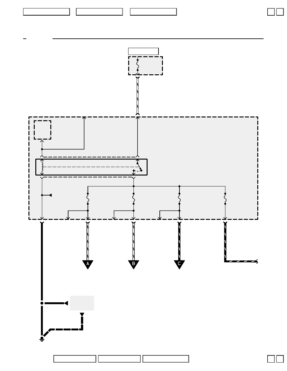
120
Power Windows
See Ground
Distribution,
page 14-8.
BLK
BLK
POWER
WINDOW
40A
C307
4
C330
2
C651
18
WHT/GRN
G401
UNDER-HOOD
FUSE/RELAY
BOX
A
11
C402
8
POWER WINDOW
RR-L
20A
C403
13
C402
3
POWER WINDOW
RR-R
20A
C402
10
POWER WINDOW
MPCS
20A
C405
4
C402
1
POWER WINDOW
FR-R
20A
C406
4
C403
5
(Not used)
See Ground
Distribution,
page 14-8.
(Not
used)
UNDER-DASH
FUSE/RELAY BOX
POWER
WINDOW
RELAY
DRIVER’S
MULTIPLEX
CONTROL
UNIT
(Not
used)
(Not
used)
To page
120-3.
To page
120-2.
To page
120-3.
GRN/WHT
YEL/BLK
WHT/BLK
WHT/YEL
BLK
Power
window
relay
control
‘96-‘97
HOT AT ALL TIMES
2004 American Honda Motor Co., Inc.
▲
▲
Нет комментариевНе стесняйтесь поделиться с нами вашим ценным мнением.
Текст