Acura RL (1996-2004 year). Manual — part 50
23-10
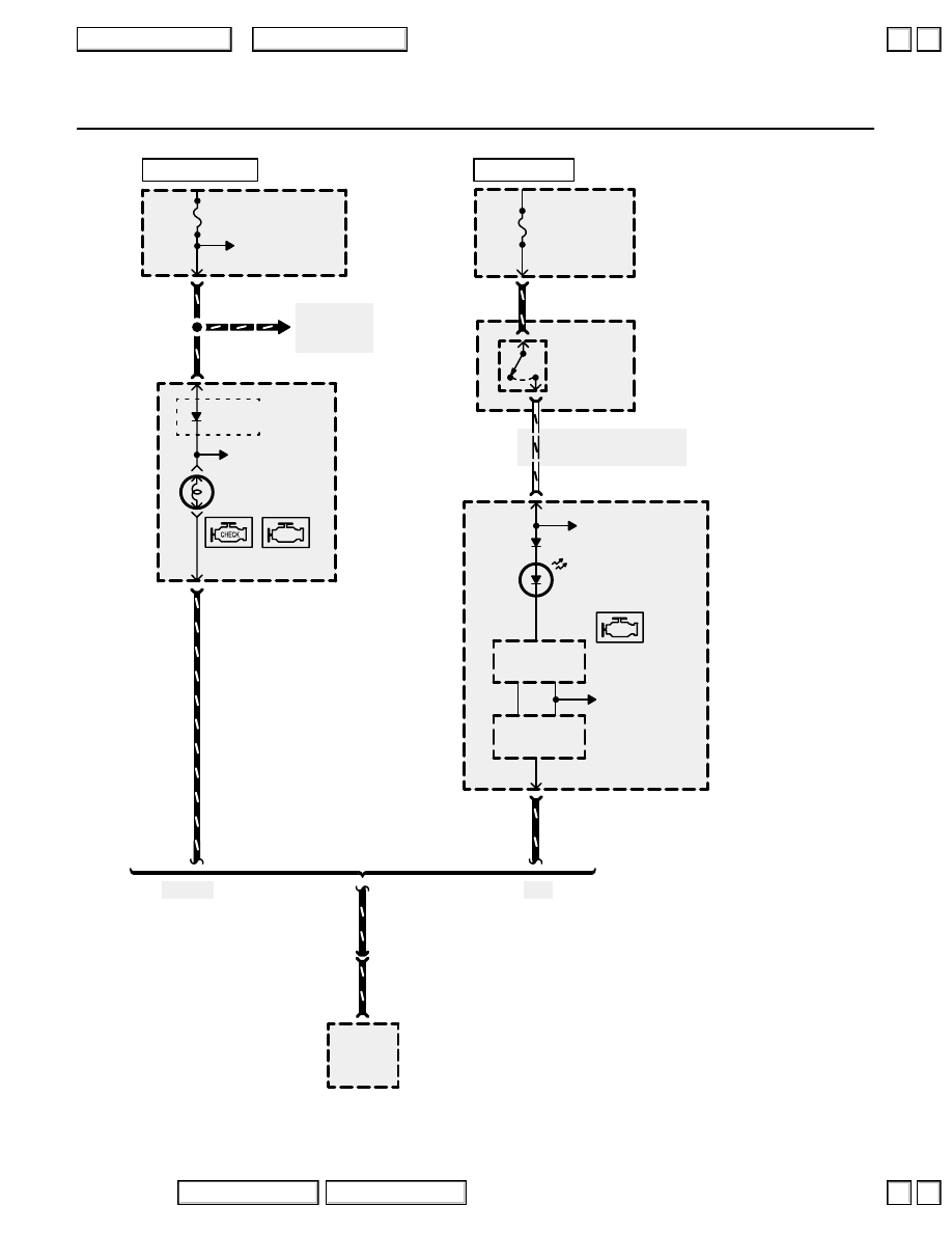
Programmed Fuel Injection System (PGM-FI)
ECU
20A
UNDER-DASH
FUSE/RELAY
BOX
A
11
BLK/YEL
See Gauge
Assembly
MALFUNCTION
INDICATOR
LAMP (MIL)
GAUGE
ASSEMBLY
LT GRN/RED
A
4
See Power
Distribution,
page 10-9.
See Power
Distribution,
page 10-9.
Canada
C502
1
BLK/YEL
‘97-‘03
USA
HOT IN ON OR START
METER
15A
C307
1
UNDER-HOOD
FUSE/RELAY
BOX
RED/YEL
See Gauge Assembly,
page 80-9.
WHT/RED
WHT/RED
A
22
GAUGE
RELAY
1
2
UNDER-HOOD
RELAY BOX C
GAUGE
ASSEMBLY
A
4
See Gauge
Assembly
HOT AT ALL TIMES
LT GRN/RED
’96-’03
’04
POWERTRAIN
CONTROL
MODULE (PCM)
A
11
C476
LT GRN/RED
(MIL)
MIL
control
LT GRN/RED
Drive
Circuit
Main
Circuit
See Gauge
Assembly
NOTE: The Gauge Relay is
energized with the ignition
switch in ON (II) or START
(III). See Gauge Assembly,
page
MALFUNCTION
INDICATOR
LAMP (MIL)
2004 American Honda Motor Co., Inc.
▼
▼
33
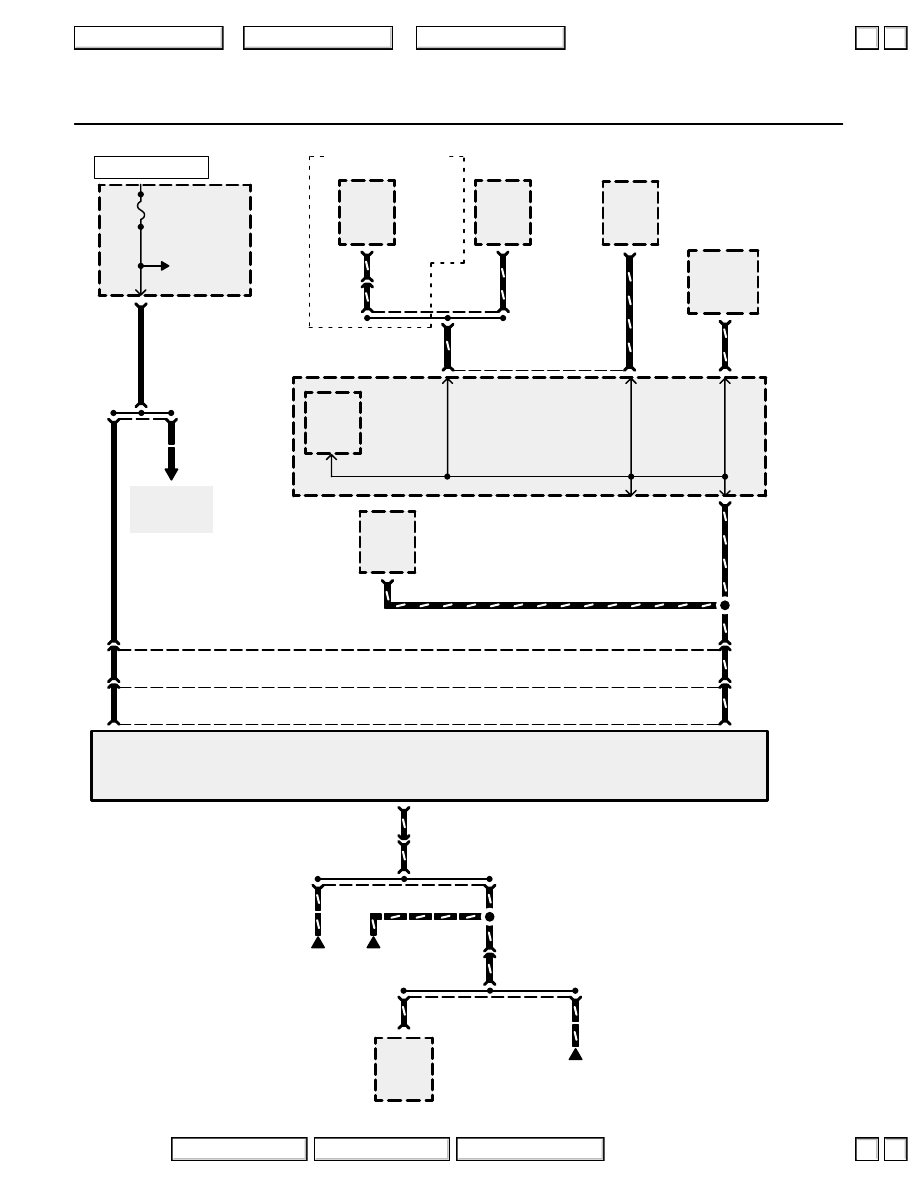
Vehicle Speed Sensor (VSS)
(
B
(C
***
)
METER (
*
)
METER
SUN ROOF (
**
)
7.5A
UNDER-
DASH
FUSE/
RELAY
BOX
See Power
Distribution,
page 10-10.
YEL
8
C404
See Power
Distribution,
page 10-10.
YEL
2
3
5
4
C123
Ignition
input
Vehicle
speed
output
VEHICLE
SPEED
SENSOR
(VSS)
YEL
BLU/WHT
C448
(Terminals 14-16)
2
1
C101
YEL
C448
(Terminals 11-13)
UNDER-
DASH
FUSE/
RELAY
BOX
4
A
DRIVER’S
MULTIPLEX
CONTROL
UNIT
14
C651
C402
7
(Not
used)
C502
13
Vehicle
speed
input
(VSS)
B
BLU/WHT
BLU/WHT
BLU/WHT
8
C403
21
Vehicle
speed
input
Vehicle
speed
input
Odometer
driver
circuit
Vehicle
speed
input
NAVI-
GATION
UNIT
PHOTO 160
(’96-’03)
PHOTO 208
VIEW 104
6
11
A
GAUGE
ASSEMBLY
PHOTO 71
(’96-’03)
PHOTO 212
VIEW 113
18
A
STEERING
COLUMN
CONTROL
UNIT
CRUISE
CONTROL
UNIT
BLU/WHT
BLU/WHT
BLU/WHT
BLU/WHT
BLU/WHT
BLU/WHT
12
5
C443
BLU/WHT
Navigation System
Vehicle
speed
input
POWERTRAIN
CONTROL
MODULE
(PCM)
*
= ‘96-‘98
**
= ’99-’04
***
= ’00-’04
C114
(Terminals 8-14)
Ground
(SG2)
Sensor
ground
D
GRN/BLU
POWERTRAIN
CONTROL
MODULE (PCM)
1
6
C123
GRN/BLU
1
C103
GRN/BLK
GRN/BLK
GRN/BLK
GRN/BLK
C456
(Terminals 17-20)
HOT IN ON OR START
2004 American Honda Motor Co., Inc.
▲
▼
▲
▼
+
–
33-1
Vehicle Speed Sensor (VSS)
How the Circuit Works
With the ignition switch in ON (II) or START (III),
battery voltage is supplied through fuse 13 and the
YEL wire to the vehicle speed sensor (VSS). The
sensor is grounded through the PCM. The
speedometer and other control units in the circuit
supply 5 volts or more to the BLU/WHT wire. The
vehicle speed sensor (VSS) intermittently grounds
the BLU/WHT wire which generates a pulsed signal
in it. The number of pulses per minute
increases/decreases with the speed of the car.
Refer to the Service Manual (Section 23, Electrical)
for specific tests or troubleshooting procedures.
2004 American Honda Motor Co., Inc.
▲
▼
▲
▼
34
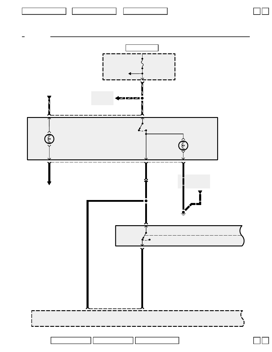
Cruise Control
’96-’98
G401
BLK
BLK
See Ground
Distribution,
page 14-9.
UNDER-DASH
FUSE/RELAY
BOX
CRUISE
CONTROL
MAIN SWITCH
Cruise control
main switch
input
Brake
switch
input
C502
ECU
20A
RED/BLK
1
3
1
CRUISE CONTROL
MAIN SWITCH
LIGHT
“ON”
INDICATOR
LIGHT
ON
OFF
2
RED
13
4
5
See Power
Distribution,
page 10-9.
BLK/YEL
LT GRN
C430
5
LT GRN
1
2
2
LT GRN
GRY
Open with
brake pedal
depressed.
BLK/YEL
See Power
Distribution,
page 10-8.
LT GRN
HOT IN ON OR START
2004 American Honda Motor Co., Inc.
▲
▲
Нет комментариевНе стесняйтесь поделиться с нами вашим ценным мнением.
Текст