Acura RL (1996-2004 year). Manual — part 265
System Description
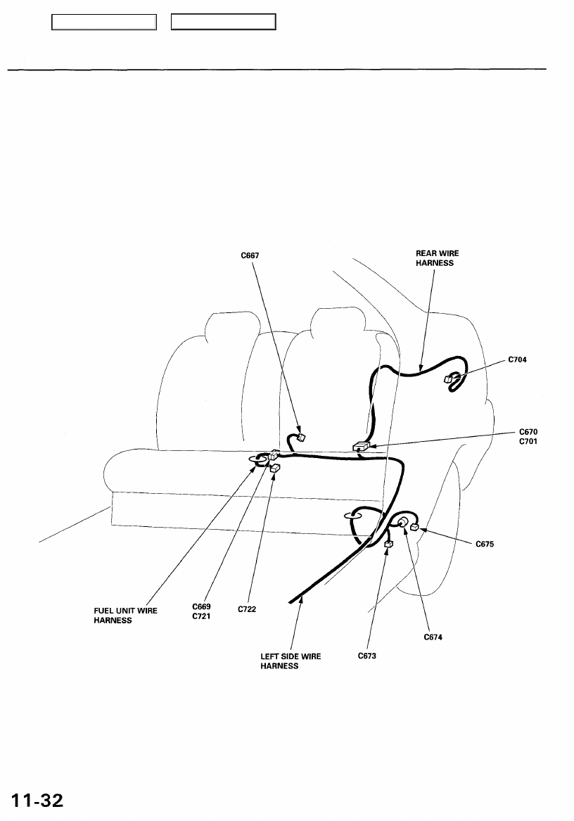
System Connectors [Dash and Floor] (cont'd)
Main Menu
Table of Contents
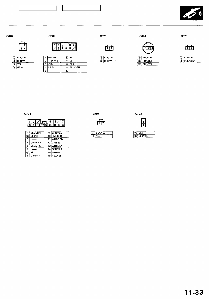
NOTE: • Different wires with the same color have been given a number suffix to distinguish them (for example, YEL/BLK
1
and YEL/BLK
2
are not the same).
• — Connector with male terminals (double outline): View from terminal side
— Connector with female terminals (single outline): View from wire side
• Related to Fuel and Emissions System.
Main Menu
Table of Contents
Troubleshooting
Troubleshooting Procedures
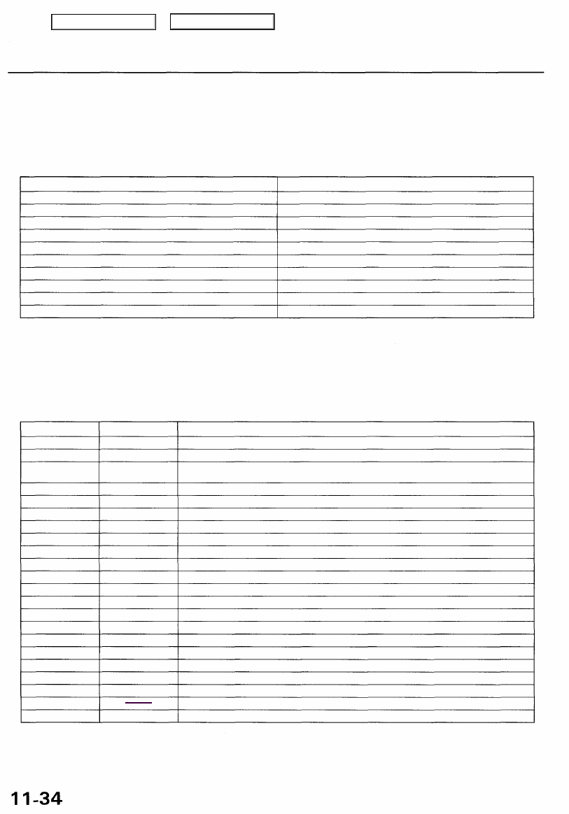
Symptom Chart
Listed below are symptoms and probable causes for problems that DO NOT cause the Malfunction Indicator Lamp (MIL) to
come on. If the MIL was reported on, check the DTC.
Troubleshoot each probable cause in the order listed (from left to right) until the symptom is eliminated.
The probable cause and troubleshooting page reference can be found below.
SYMPTOM
Engine will not start
Hard starting
Cold fast idle too low
Cold fast idle too high
Idle speed fluctuates
Misfire or rough running
Low power
Engine stalls
Difficult to refuel
Fuel overflows during refueling
PROBABLE CAUSE
2, 3, 21, 13, 1
2, 10, 12, 20, 21
5, 6, 7, 4
5, 6, 7, 9, 8
5, 14, 15, 6, 7, 9, 8
Troubleshoot for misfire on pages
2, 8, 9, 11, 18,17, 19, 10
2, 5, 10, 21, 7, 3, 16
20, 22
20, 22
Other Probable Causes for an engine that will not start:
— Compression — Starting system
— PGM-FI main relay — Ignition system
— Engine locked up — Overheating
— Timing belt — Battery
Probable Cause
1
2
3
4
5
6
7
8
9
10
11
12
13
14
15
16
17
18
19
20
21
22
Page
(see DTC chart)
(see DTC chart)
(see DTC chart)
(see DTC chart)
System
Powertrain Control Module (PCM)
Fuel pressure
Crankshaft Position/Camshaft Position (CKP/CMP) (Crankshaft Position/Cylinder Position
(CKP/CYP)) sensor circuit
Intake Air Temperature (IAT) sensor circuit
Idle Air Control (IAC) valve
Idle Air Control (IAC) thermal valve
Idle speed adjustment
Throttle body
Throttle cable
Manifold Absolute Pressure (MAP) sensor
Throttle Position (TP) sensor
Barometric pressure (BARO) sensor
Transmission range switch signal
Air conditioning signal
Alternator FR Signal
Brake pedal position switch signal
Air cleaner
Intake Manifold Runner Control (IMRC) system and intake air duct
Three Way Catalytic Converter (TWC)
Evaporative emission (EVAP) control
Contaminated fuel
Fuel tank vapor control valve
Probable Cause List (For the DTC Chart, see page
(see DTC chart)
(see DTC chart)
(see DTC chart)
(see DTC chart)
Main Menu
Table of Contents
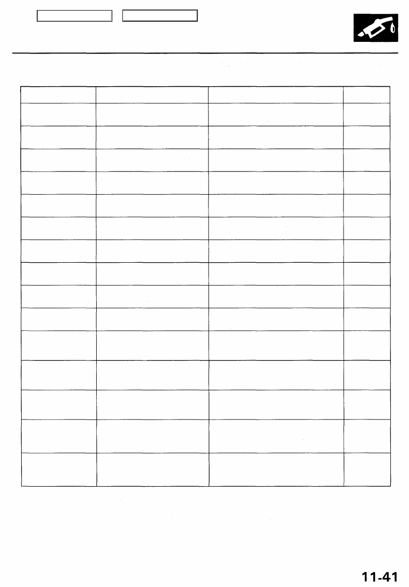
Diagnostic Trouble Code (DTC) Chart
DTC
(MIL indication*
1
)
P0107 (3)
P0108 (3)
P0112 (10)
P0113 (10)
P0116 (86)*
2
P0117 (6)
P0118 (6)
P0122 (7)
P0123 (7)
P0125 (86)*
2
P0133 (62)*
2
P0134 (2)
P0135 (42)
P0137 (63)*
2
P0138 (63)*
2
Detection Item
Manifold Absolute Pressure (MAP)
Sensor Circuit Low Voltage
Manifold Absolute Pressure (MAP)
Sensor Circuit High Voltage
Intake Air Temperature (IAT) Sensor
Circuit Low Voltage
Intake Air Temperature (IAT) Sensor
Circuit High Voltage
Engine Coolant Temperature (ECT)
Sensor Range/Performance
Problem
Engine Coolant Temperature (ECT)
Sensor Circuit Low Voltage
Engine Coolant Temperature (ECT)
Sensor Circuit High Voltage
Throttle Position (TP) Sensor Circuit
Low Voltage
Throttle Position (TP) Sensor Circuit
High Voltage
Engine Coolant Temperature (ECT)
Sensor Slow Response
Right Primary Heated Oxygen
Sensor (Right Primary H02S) Slow
Response (Bank 1, Sensor 1)
Right Primary Heated Oxygen
Sensor (Right Primary HO2S) Heater
System Malfunction
Right Primary Heated Oxygen
Sensor (Right Primary H02S) Heater
Circuit Malfunction (Bank 1,
Sensor 1)
Secondary Heated Oxygen Sensor
(Secondary H02S) Circuit Low
Voltage (Sensor 2)
Secondary Heated Oxygen Sensor
(Secondary H02S) Circuit High
Voltage (Sensor 2)
Probable Cause
• Open or short in MAP sensor circuit
• MAP sensor
• PCM
• Open in MAP sensor circuit
• MAP sensor
• PCM
• Short in IAT sensor circuit
• IAT sensor
• PCM
• Open in IAT sensor circuit
• IAT sensor
• PCM
• ECT sensor
• Cooling system
• Short in ECT sensor circuit
• ECT sensor
• PCM
• Open in ECT sensor circuit
• ECT sensor
• PCM
• Open or short in TP sensor circuit
• TP sensor
• PCM
• Open in TP sensor circuit
• TP sensor
• PCM
• ECT sensor
• PCM
• Right Primary H02S (Bank 1, Sensor 1)
• Exhaust system
• Open in Right Primary H02S (Bank 1,
Sensor 1) circuit
• Right Primary HO2S (Bank 1, Sensor 1)
• PCM
• Open or short in Right Primary H02S
(Bank 1, Sensor 1) heater circuit
• PCM
• Short in Secondary H02S (Sensor 2)
circuit
• Secondary H02S (Sensor 2)
• PCM
• Open in Secondary H02S (Sensor 2)
circuit
• Secondary HO2S (Sensor 2)
• PCM
Page
*1: These DTCs will be indicated by the blinking of the Malfunction Indicator Lamp (MIL) with the SCS service connector
connected.
*2: These DTCs require two "trips" or two driving cycles unless the SCS service connector is connected.
(cont'd)
Main Menu
Table of Contents
Нет комментариевНе стесняйтесь поделиться с нами вашим ценным мнением.
Текст