Acura RL (1996-2004 year). Manual — part 507
Troubleshooting
DTC 1-2: Pump Motor
The ABS control unit checks the conditions at the pump motor relay drive (PMR) terminal and motor check (MCK) terminal
during the initial diagnosis and regular diagnosis. When the ABS control unit detects the following conditions during the
diagnosis, it keeps the ABS indicator light on. When the following conditions are detected after the ABS indicator light
goes off, the ABS control unit turns the ABS indicator light on again.
Battery voltage at the MCK terminal with an OFF signal at the PMR terminal
O V at the MCK terminal with an ON signal at the PMR terminal
Possible causes:
Open circuit or short to body ground between the R/C MIRROR (7.5 A) fuse and under-hood fuse/relay box
Open circuit or short to body ground in the PMR circuit inside the under-hood fuse/relay box
Faulty pump motor relay
Open circuit or short to body ground in the PMR circuit between the under-hood fuse/relay box and ABS control unit
Open circuit between the battery and under-hood fuse/relay box
Blown ABS MOTOR (40 A) fuse
Blown ABS UNIT (7.5 A) fuse
Open circuit or short to body ground in the motor drive circuit and MCK circuit inside the under-hood fuse/relay box
Open circuit or short to body ground in the MCK circuit between the under-hood fuse/relay box and ABS control unit
Open circuit or short to body ground between the under-hood fuse/relay box and pump motor
Faulty pump motor
Open circuit between the pump motor and body ground or poor ground
Faulty ABS control unit
With engine running, ABS indi-
cator light is ON.
With the SCS service connec-
tor connected (see page
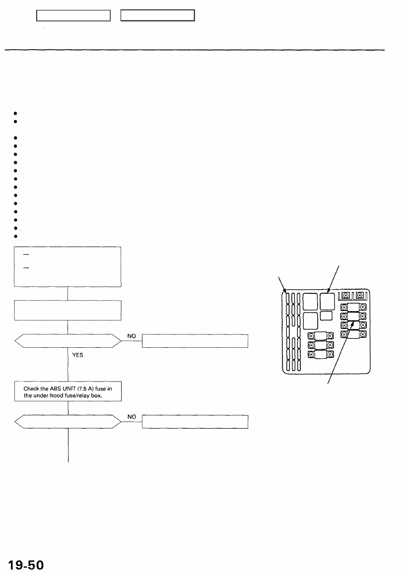
UNDER-HOOD FUSE/RELAY BOX
ABS PUMP MOTOR RELAY
ABS UNIT (7.5 A) FUSE
Check the ABS MOTOR (40 A) fuse
in the under-hood fuse/relay box.
Is the fuse OK?
Replace the fuse and recheck.
NOTE: Reinstall the fuse if it is OK.
ABS MOTOR (40 A) FUSE
Is the fuse OK?
Replace the fuse and recheck.
YES
NOTE: Reinstall
the fuse if it is OK.
NOTE: Relieve system pressure from the
modulator unit bleed screw, then start the
engine and recheck the fuse. If the fuse is
blown, check for a short to body ground in
the MCK circuit.
Main Menu
Table of Contents
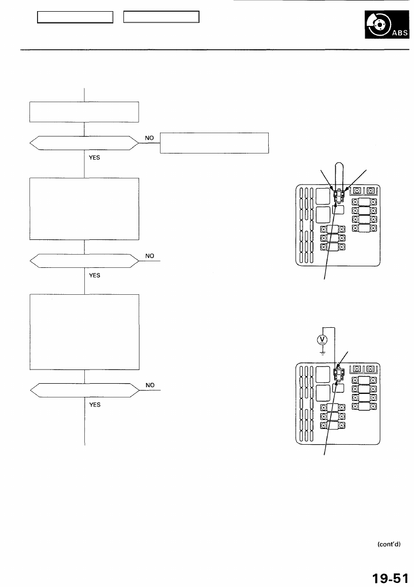
Remove the ABS pump motor
relay and check it (see
).
Is the relay OK?
Check the ABS pump motor oper-
ation:
1. Relieve system pressure (see
page 19-97).
2. Connect the ABS pump relay
connector +B and MOTOR ter-
minals with a jumper wire for
1 second.
Does the pump motor run?
Check the MCK (motor check) cir-
cuit:
1. Remove the jumper wire.
2. Disconnect the under-hood
fuse/relay box 3P connector.
3. Turn the ignition switch ON (II).
4. Measure the voltage between
the ABS pump motor relay
connector motor terminal and
body ground.
Is there about 10V?
Replace the ABS pump motor
relay.
NOTE: If the relay is stuck ON, the motor may
be damaged. Check the pump motor opera-
tion.
UNDER-HOOD FUSE/RELAY BOX
JUMPER WIRE
NOTE: Use a jumper wire with a diameter
larger than 2 mm (0.08 in).
To check for an open in the pump
motor drive circuit
ABS PUMP MOTOR RELAY CONNECTOR
To check for an open in the MCK
circuit
MOTOR TERMINAL
ABS PUMP MOTOR RELAY CONNECTOR
+B TERMINAL
MOTOR TERMINAL
Main Menu
Table of Contents
Troubleshooting
DTC 1-2: Pump Motor (cont'd)
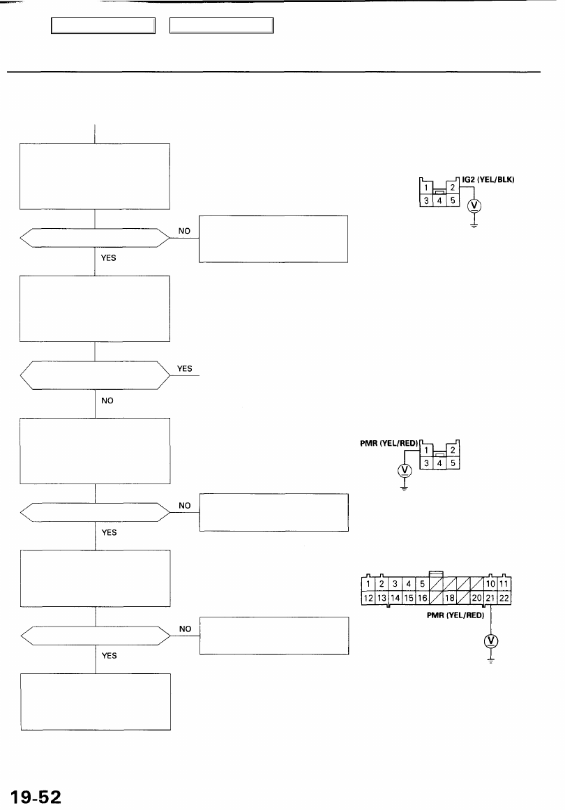
Check for an open in the IG2 cir-
cuit:
Measure the voltage between the
under-hood fuse/relay box 5P
connector terminal No. 2 and
body ground.
Is there battery voltage?
Check the ABS pump motor relay
operation:
1. Connect the under-hood fuse/
relay box 3P connector.
2. Install the ABS pump motor
relay.
Does the ABS pump motor
relay operate?
Check for an open in the under-
hood fuse/relay box:
Measure the voltage between the
under-hood fuse/relay box 5P
connector terminal No. 1 and
body ground.
Is there battery voltage?
Check for an open in the PMR cir-
cuit:
Measure the voltage between the
ABS control unit 22P connector
terminal No. 21 and body ground.
Is there battery voltage?
Reconnect the connectors prop-
erly, relieve system pressure and
start the engine. If DTC 1-2 is
stored again, replace the ABS
control unit.
NOTE: The ABS pump motor relay coil circuit
is checked beginning with this step.
UNDER-HOOD FUSE/RELAY BOX
5P CONNECTOR
Repair open in the wire between
the R/C MIRROR (7.5 A) fuse in the
under-dash fuse/relay box and the
under-hood fuse/relay box.
Wire side of female terminals
To check for a short to body ground
in the ABS pump motor relay coil cir-
cuit
NOTE: The ABS pump motor relay coil circuit
is checked for an open beginning with this
step.
UNDER-HOOD FUSE/RELAY BOX
5P CONNECTOR
Replace the under-hood fuse/
relay box.
(Open circuit inside the box)
Wire side of female terminals
ABS CONTROL UNIT 22P CONNECTOR
Repair open in the wire between
the under-hood fuse/relay box
and ABS control unit.
NOTE: Add brake fluid if the fluid level is
lower than the MIN line.
Wire side of female terminals
Main Menu
Table of Contents
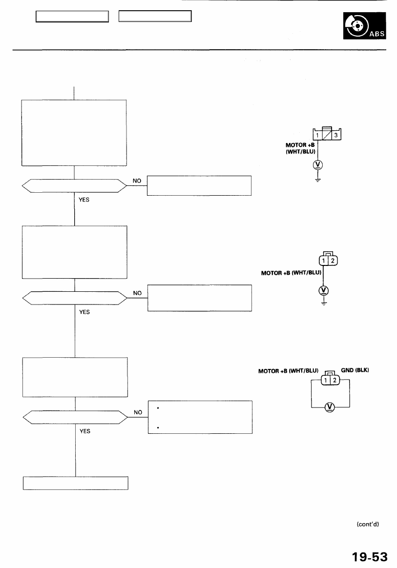
Check for an open in the under-
hood fuse/relay box:
1. Connect the ABS pump motor
relay connector +B and MOTOR
terminals with a jumper wire.
2. Measure the voltage between
the under-hood fuse/relay box
3P connector terminal No. 1
and body ground.
NOTE: The ABS pump motor drive circuit is
checked beginning with this step.
UNDER-HOOD FUSE/RELAY BOX
3P CONNECTOR
Is there battery voltage?
Replace the under hood fuse/
relay box.
Wire side of female terminals
ABS PUMP MOTOR 2P CONNECTOR
Is there battery voltage?
Repair open in the wire between
the under-hood fuse/relay box
and ABS pump motor.
Wire side of female terminals
Check for an open in the MOTOR
GND circuit:
Measure the voltage between the
ABS pump motor 2P connector
terminals No. 1 and No. 2.
Is there battery voltage?
Repair open in the wire between
the ABS pump motor and body
ground.
Repair poor ground (G251)
Replace the ABS pump motor.
Check for an open in the MOTOR
+B circuit:
1. Disconnect the ABS pump
motor 2P connector.
2. Measure the voltage between
the terminal No. 1 and body
ground.
Main Menu
Table of Contents
Нет комментариевНе стесняйтесь поделиться с нами вашим ценным мнением.
Текст