Acura RL (1996-2004 year). Manual — part 105
+
–
138-1
Interlock System
How the Circuit Works
Key Interlock
Battery voltage is supplied at all times through fuse
39 to the key interlock switch. When you put the key
in the ignition, battery voltage is supplied to the key
interlock solenoid and the driver’s multiplex control
unit. When you move the A/T shift lever to PARK and
release the push button, the driver’s multiplex control
unit removes ground from the key interlock solenoid,
the solenoid is deenergized, and the key can be
removed from the ignition.
Shift Position Interlock
Battery voltage is supplied at all times through fuse
39 to the brake pedal position switch. With the
ignition in ON (II) or START (III), battery voltage is
supplied through fuse 20 to the shift lock solenoid.
When you push the brake pedal, battery voltage is
applied through the GRN/WHT wire to the
powertrain control module (PCM). If, at the same
time, you do not push the accelerator pedal, a low
voltage signal is sent through the RED/BLK wire to
the PCM. The PCM then applies voltage through
the WHT/GRN wire to the shift lock circuit in the
driver’s multiplex control unit. If the shift lever is in
the PARK position, the shift lock circuit provides
ground to the shift lock solenoid. The solenoid is
then energized and the shift lever can be moved
from the PARK position.
Refer to the Service Manual (Section 14, Automatic
Transmission) for specific tests or troubleshooting
procedures.
2004 American Honda Motor Co., Inc.
▲
▼
▲
▼
140
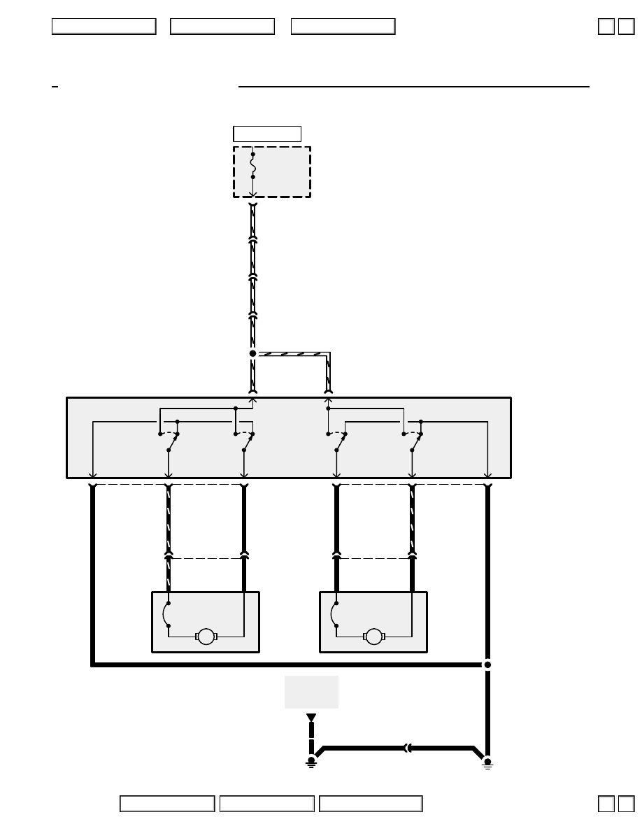
Power Seats
Front Passenger’s Seat
B
POWER
SEAT AS
30A
C307
9
7
A
8
1
WHT/RED
WHT/RED
WHT/RED
UNDER-HOOD
FUSE/RELAY
BOX
FRONT
PASSENGER’S
POWER SEAT
SWITCH
5
6
BACKWARD
FORWARD
BACKWARD
FORWARD
3
1
4
B
M
M
A
4
C612
WHT/RED
SLIDE
MOTOR
BLK
2
RECLINE
MOTOR
C645
2
1
C644
2
1
BLK
YEL/RED
YEL
RED
RED/YEL
BLK
RED
BLK
BLU
BLU/YEL
See Ground
Distribution,
page 14-14.
G601
, Driver’s Position Memory System (DPMS), for Driver’s Power Seat circuit schematic.
G641
17
WHT/RED
C442
17
WHT/RED
C325
BLK
BLK
C612
HOT AT ALL TIMES
2004 American Honda Motor Co., Inc.
▲
▲
+
–
140-1
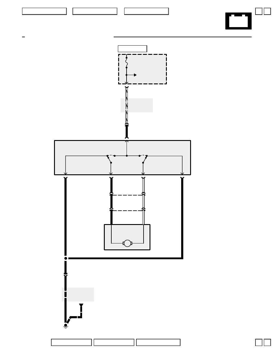
Power Seats
See Power
Distribution,
page 10-3.
See Ground
Distribution,
page 14-16.
’04 Lumbar Support System
DR POWER SEAT
RECLINING + RR HEIGHT
20A
C651
15
4
5
GRN
WHT/RED
UNDER-DASH
FUSE/RELAY
BOX
LUMBAR
SUPPORT
SWITCH
BACKWARD
FORWARD
5
2
1
M
C659
LUMBAR
SUPPORT
MOTOR
12
BLK
WHT
RED
BLK
C659
See Power
Distribution,
page 10-3.
WHT/RED
3
BLK
BLK
BLK
G651
2
C694
1
WHT
YEL
2
1
WHT
YEL
HOT AT ALL TIMES
2004 American Honda Motor Co., Inc.
▼
▼
140-2
Power Seats
How the Circuit Works
Front Passenger’s Seat
Power is supplied to the front passenger’s power
seat switch through fuse 52 at all times.
Slide
When you push the slide switch to the FORWARD
position, voltage is supplied to the slide motor
through the RED/YEL wire, and the motor runs,
moving the seat forward. With the switch in
FORWARD, the slide motor is grounded through the
RED wire and the normally closed contacts of the
backward switch.
When you move the slide switch to the
BACKWARD position, voltage is supplied to the
slide motor through the RED wire, and the motor
runs, moving the seat back. With the switch in
BACKWARD, the slide motor is grounded through
the RED/YEL wire and the normally closed contacts
of the forward switch.
Recline
When you push the recline switch to the FORWARD
position, voltage is supplied to the recline motor
through the YEL wire, and the motor runs, tilting the
seatback forward. With the switch in FORWARD,
the recline motor is grounded through the YEL/RED
wire and the normally closed contacts of the
backward switch.
When you push the recline switch to the
BACKWARD position, voltage is supplied to the
recline motor through the YEL/RED wire, and the
motor runs, tilting the seatback back. With the
switch in BACKWARD, the recline motor is
grounded through the YEL wire and the normally
closed contacts of the forward switch.
Refer to the Service Manual (Section 23, Electrical)
for specific tests or troubleshooting procedures.
Lumbar Support
Power is supplied to the lumbar support switch
through fuse 8 at all times.
When you push the lumbar support switch to the
FORWARD position, voltage is supplied to the
lumbar motor through the GRN wire, and the motor
runs, inflating the lumbar. With the switch in
FORWARD, the lumbar support motor is grounded
through the BLK wire and the normally closed
contacts of the backward switch.
When you push the lumbar support switch to the
BACKWARD position, voltage is supplied to the
lumbar motor through the GRN wire, and the motor
runs, deflating the lumbar. With the switch in
BACKWARD, the lumbar support motor is
grounded through the BLK wire and the normally
closed contacts of the forward switch.
2004 American Honda Motor Co., Inc.
▲
▼
▲
▼
Нет комментариевНе стесняйтесь поделиться с нами вашим ценным мнением.
Текст