Acura RL (1996-2004 year). Manual — part 69
74-2
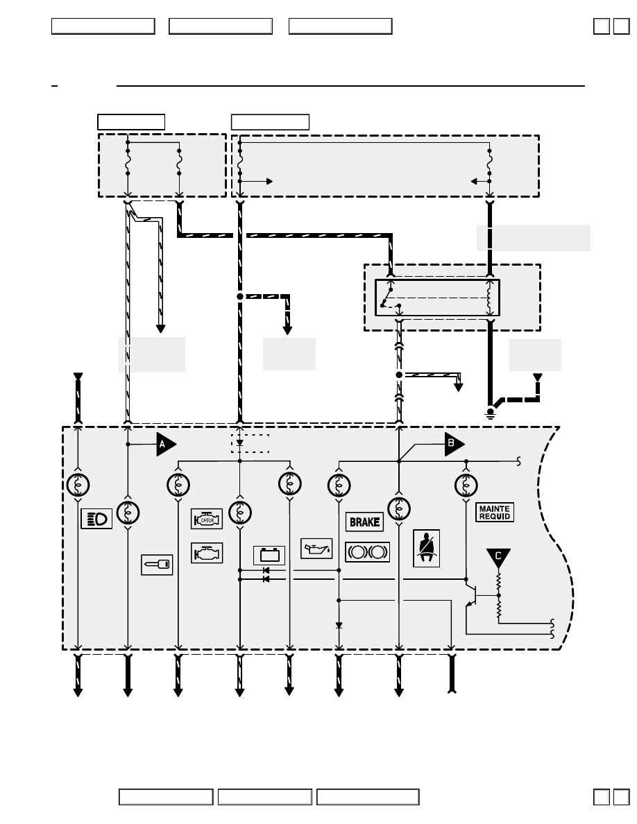
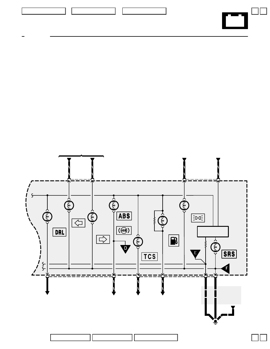
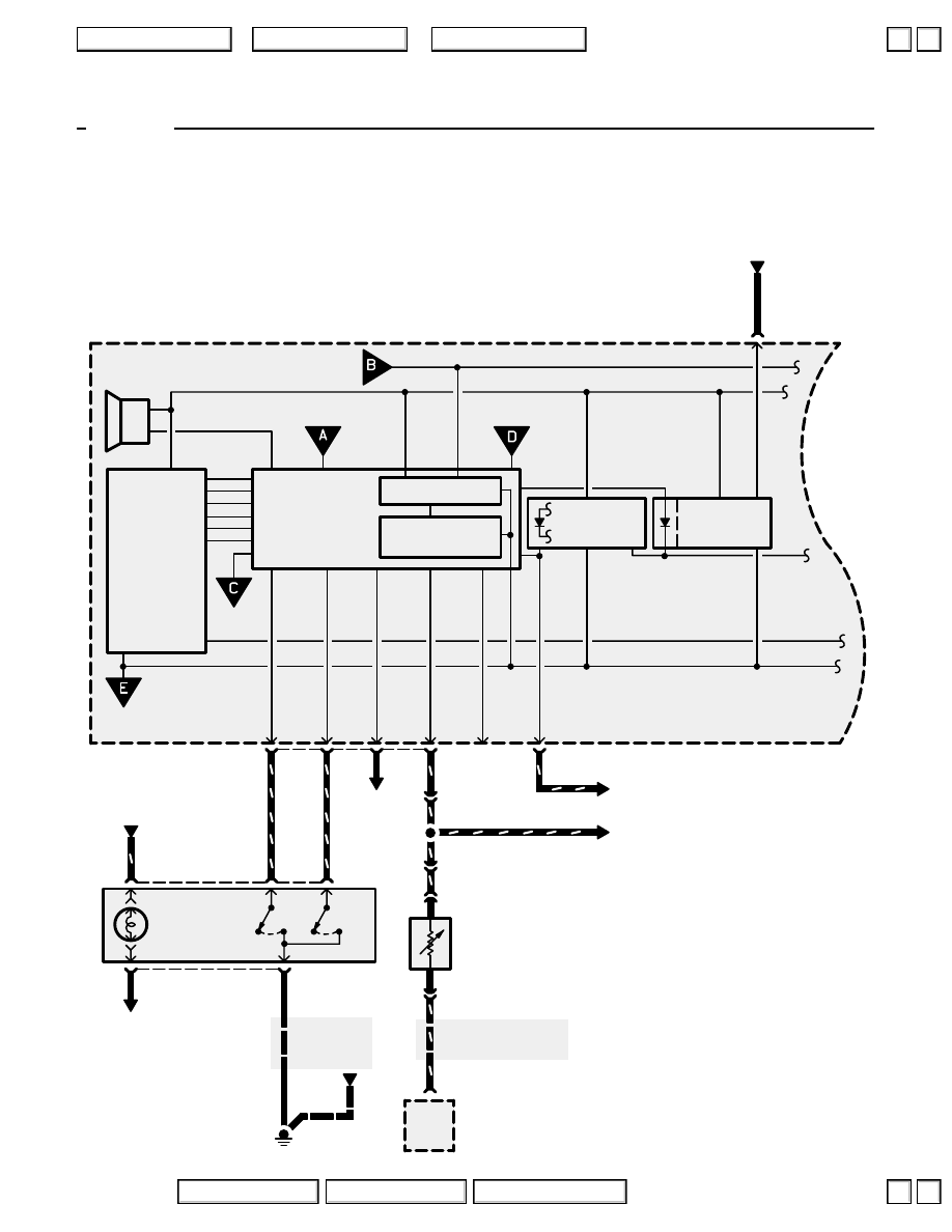
Low Fuel Indicator Light
How the Circuit Works
WARNING
Do not smoke while working on the fuel system.
Keep open flame away from the work area.
Drain fuel only into an approved container.
’96-’03
A thermistor is mounted in the fuel tank unit. When
the thermistor is cool, its resistance is very high.
When the thermistor is warm, its resistance
decreases. Fuel in the fuel tank transfers heat away
from the thermistor fast enough to keep it cool so
the thermistor’s resistance stays high and the low
fuel indicator light does not come on. When the fuel
level drops below about 2.2 gallons, the thermistor
is no longer immersed in fuel. Without the fuel to
cool it, the thermistor’s resistance decreases,
allowing current to flow through the low fuel
indicator light and the thermistor to ground, and the
low fuel indicator light comes on.
Refer to the Service Manual (Section 23, Electrical)
for specific tests or troubleshooting procedures.
2004 American Honda Motor Co., Inc.
▲
▼
▲
▼
80
Gauge Assembly
C477
See Power
Distribution,
page 10-15.
7
C502
C307
1
A
C325
WHT/RED
WHT/RED
WHT/RED
1
9
22
UNDER-
DASH
FUSE/
RELAY
BOX
IMMOBI-
LIZER
SYSTEM
INDICA-
TOR
LIGHT
BACK UP
RADIO
7.5A
See Power Distribution,
page 10-10.
UNDER-HOOD
FUSE/RELAY
BOX
C331
2
3
See Ground
Distribution,
page 14-6.
G301
5
BLK
GAUGE
RELAY
UNDER-
HOOD
RELAY
BOX C
6
WHT/YEL
YEL
YEL
ECU
20A
See Power
Distributon,
page 10-10.
METER
7.5A
1
11
BLK/YEL
WHT/RED
2
RED/YEL
P
!
– +
To page
80-2.
SEAT
BELT
REMINDER
LIGHT
MAINTE-
NANCE
REMINDER
LIGHT
From C on
page 80-2.
BRAKE
SYSTEM
INDICA-
TOR
LIGHT
To page
80-2.
USA
Canada
CHARG-
ING
SYSTEM
INDICA-
TOR
LIGHT
HI
BEAM
INDICA-
TOR
LIGHT
USA
Canada
MAL-
FUNCTION
INDICATOR
LIGHT
(MIL)
B
20
RED/
GRN
21
RED/BLU
5
See
Brake
System
Indicator
Light
GRN/RED
A
5
WHT/BLU
4
LT GRN/RED
B
19
PNK
16
RED/
BLU
METER
15A
See Power
Distributon,
page 10-8.
See Power
Distribution,
page 10-9.
WHT/YEL
BLK/YEL
5
WHT/RED
WHT/
YEL
‘96-‘97
LOW
EN-
GINE
OIL
PRES-
SURE
INDI-
CATOR
LIGHT
3
See
Engine Oil
Pressure
Indicator
Light
YEL/RED
’97
7
(Not
used)
B
C476
14
GRY
HOT IN ON OR START
HOT AT ALL TIMES
2004 American Honda Motor Co., Inc.
▲
▲
+
–
80-1
Gauge Assembly
‘96-‘97
RIGHT
TURN
SIGNAL
INDICA-
TOR
LIGHT
From
page
80-3.
LEFT
TURN
SIGNAL
INDICA-
TOR
LIGHT
13
PNK/BLU
A
12
GRN/YEL
TCS
INDICA-
TOR
LIGHT
ABS
INDICA-
TOR
LIGHT
7
BLU/GRY
22
BLU/WHT
LOW
FUEL
INDICA-
TOR
LIGHT
A
8
BLU/RED
SRS
INDICATOR
LIGHT
LIGHTS-
ON
INDICATOR
LIGHT
18
RED/BLK
B
15
BLU/WHT
See Ground
Distribution,
pages 14-8
and 14-9.
10
G401
9
BLK
BLK
BLK
BLK
From
page
80-2.
To page
80-2.
B
GAUGE
ASSEMBLY
(USA)
(Canada)
SRS Indicator
Circuit
17
YEL
DRL
INDICA-
TOR
LIGHT
2004 American Honda Motor Co., Inc.
80-2
Gauge Assembly
SELECT/
RESET
SWITCH
A
BRN/WHT
From
page 80.
A
1
BLU
SELECT/
RESET
SWITCH
LIGHT
5
RED/
BLK
4
RED
2
See Ground
Distribution,
page 14-8.
BLK
BLK
G401
1
GRN/WHT
15
3
BLK/
WHT
16
BRN/WHT
19
See A/C Compressor
Controls, page 60-1.
PNK/BLU
OUTSIDE AIR
TEMPERATURE
SENSOR
C201
7
BRN/WHT
BRN/
WHT
C476
9
BRN/
WHT
A
2
CLIMATE
CONTROL
UNIT
Sensor
ground
PNK/BLU
GRY
20
BLU/WHT
A
18
From
page 80-1.
(Not
used)
To page
80-1.
FIP
(Display)
ODO/
Trip
Indicator
Outside
Air
Temperature
From
page 80.
Speedometer
Drive Circuit
Main Circuits
Power Supply
Micro Computer
Non-volatile
storage
Fluorescent Light
Power Supply
Beeper
To page
80.
A
14
Select
Reset
Power Supply
Circuit
C212
1
PNK
C212
2
BLK
‘96-‘97
Protection Circuit
2004 American Honda Motor Co., Inc.
Нет комментариевНе стесняйтесь поделиться с нами вашим ценным мнением.
Текст