Acura RL (1996-2004 year). Manual — part 549
(From page
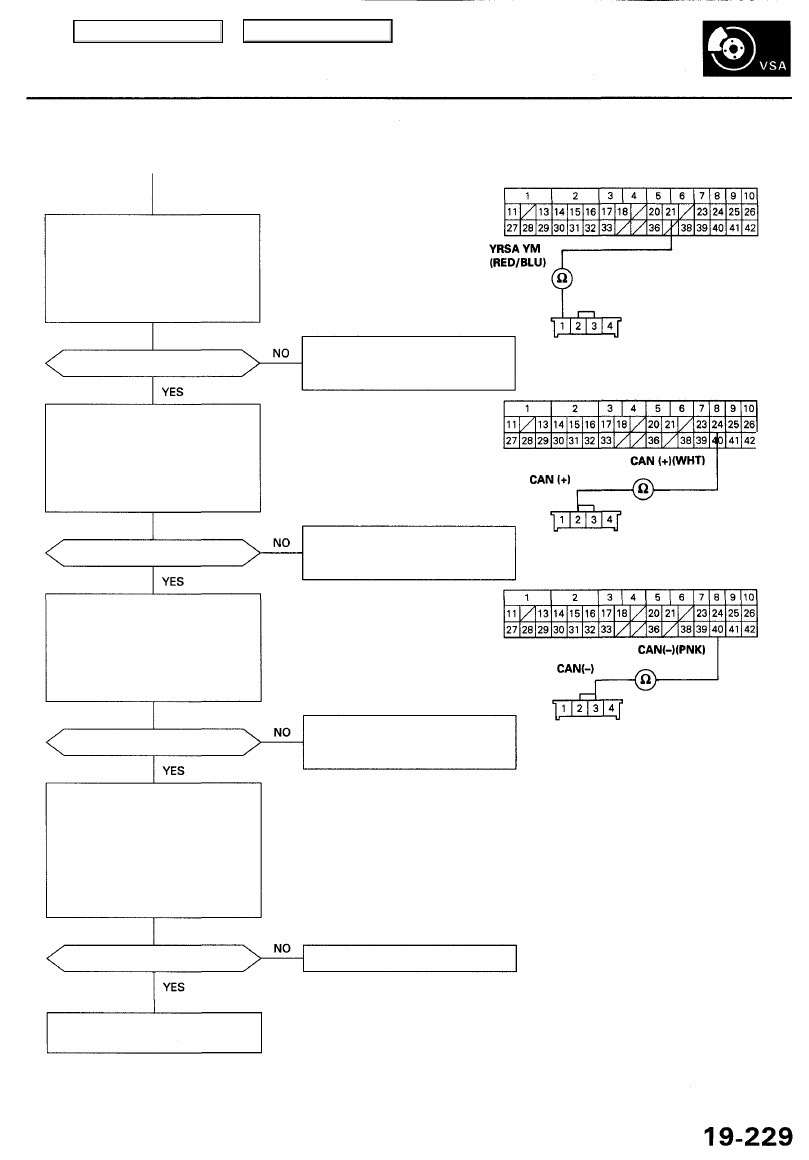
Check for an open in the YRSA
YM circuit:
Check for continuity between the
VSA control unit 42P connector
terminal No. 21 and the steering
angle sensor 4P connector termi-
nal No. 1.
Is there continuity?
Check for an open in the CAN (+)
circuit:
Check for continuity between the
VSA control unit 42P connector
terminal No. 24 and the steering
angle sensor 4P connector termi-
nal No. 2.
Is there continuity?
Check for an open in the CAN (-)
circuit:
Check for continuity between the
VSA control unit 42P connector
terminal No. 40 and the steering
angle sensor 4P connector termi-
nal No. 3.
Is there continuity?
Check the steering angle sensor:
1. Substitute a known-good
steering angle sensor.
2. Connect all of disconnected
connector.
3. Clear the DTC.
4. Test drive the vehicle around a
number of corners.
5. Verify the DTC.
Is DTC 27 indicated?
VSA CONTROL UNIT 42P CONNECTOR
Repair open in the wire between
the steering angle sensor and
the VSA control unit.
Wire side of
female terminals
STEERING ANGLE
SENSOR 4P
CONNECTOR
Wire side of female terminals
Replace the steering angle sensor.
Repair open in the wire between
the steering angle sensor and
the VSA control unit.
Repair open in the wire between
the steering angle sensor and
the VSA control unit.
Replace the VSA modulator-con-
trol unit.
YRSA YM
(RED/WHT)
(RED)
(WHT)
Main Menu
Table of Contents
Troubleshooting
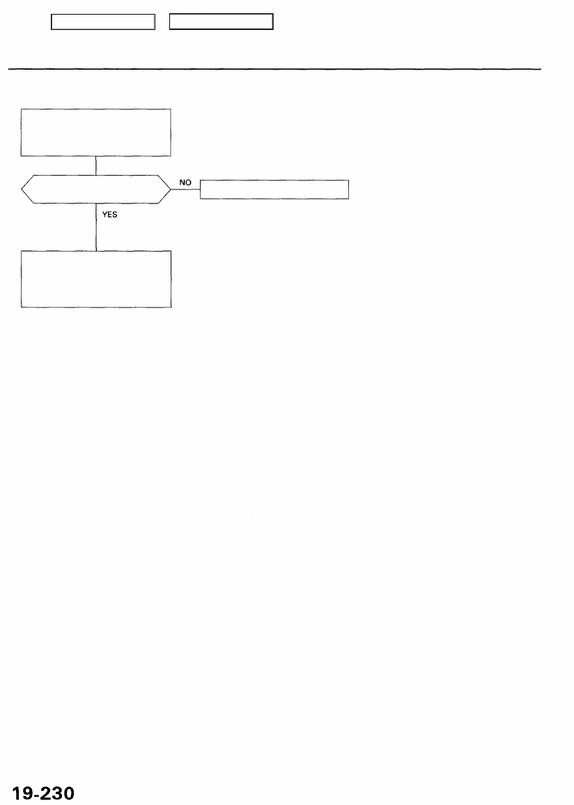
DTC 31, 32, 33, 34, 35, 36, 37, 38: ABS Solenoid
Problem verification:
1. Clear the DTC.
2. Test drive the vehicle.
3. Verify the DTC.
Are DTCs 31, 32, 33, 34, 35,
36, 37, 38 indicated?
The system is OK at this time.
Check for loose terminals in the
VSA control unit 42P connector. If
necessary, substitute a known-
good VSA modulator-control unit,
and recheck.
Main Menu
Table of Contents
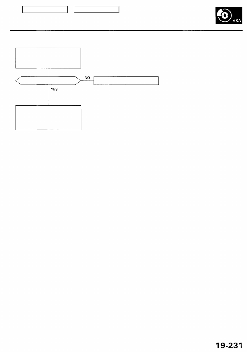
DTC 45, 46, 47, 48: VSA Solenoid
Problem verification:
1. Clear the DTC.
2. Test drive the vehicle.
3. Verify the DTC.
Are DTCs 45, 46, 47, 48 indicated?
The system is OK at this time.
Check for loose terminals in the
VSA control unit 42P connector.
If necessary, substitute a known-
good VSA modulator-control
unit, and recheck.
Main Menu
Table of Contents

Troubleshooting
DTC 51, 52, 53: Pump Motor
Check the VSA MOTOR (40 A)
fuse in the under-hood fuse/relay
box, and reinstall the fuse if it is
OK.
Is the fuse OK?
Check for an open in the +B-MR
circuit:
1. Disconnect the VSA control
unit 42P connector.
2. Measure the voltage between
terminal No. 2 and body
ground.
Is there battery voltage?
Check for an open in the M-GND
circuit:
Check for continuity between the
VSA control unit 42P connector
terminal No. 1 and body ground.
Is there continuity?
Problem verification:
1. Clear the DTC.
2. Test drive the vehicle at 12
mph (20 km/h) or more.
3. Verify the DTC.
Is DTC 51, 52 or 53 indicated?
Replace the fuse, and recheck. If
the fuse is blown, check for a
short to body ground in this fuse
circuit. If the circuit is OK,
replace the VSA modulator-con-
trol unit.
VSA CONTROL UNIT 42P CONNECTOR
Repair open in the wire between
the VSA MOTOR (40A) fuse and
the VSA control unit.
Repair open in the wire
between the VSA control unit
and body ground.
Repair poor ground (G401,
G402).
The system is OK at this time.
Check for loose terminals in the
VSA control unit 42P connector.
If necessary, substitute a known-
good VSA modulator-control
unit, and recheck.
Terminal side of female terminals
Main Menu
Table of Contents
Нет комментариевНе стесняйтесь поделиться с нами вашим ценным мнением.
Текст