Acura RL (1996-2004 year). Manual — part 201
+
–
2004 American Honda Motor Co., Inc.
Connector Views
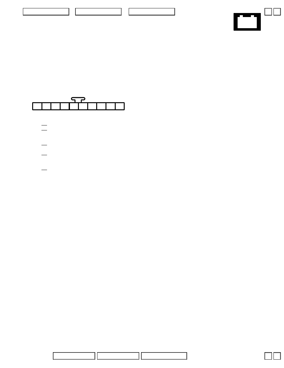
1
2
3 GRN/WHT
4 BLK/WHT
5
6 Canada: YEL
7
8 BLU/WHT
9 BLU/WHT
10
113. Gauge Assembly
– Left side of dash
– On dashboard wire harness
’04:
Connector C
– Green
1
2
3
7
5
4
6
8
9
10
▼
▼

+
–
2004 American Honda Motor Co., Inc.
Connector Views
1
2
3
4
5
6
7
8
9
10
(Multiplex control inspection
connector input)
11
12
13
14
Connector B
– Gray
– On main wire harness
3
4 RED/GRN
(Lights-on input/taillight relay control)
5 GRN
6 GRN/YEL
(Intermittent dwell timer input)
7 WHT
9 BRN/WHT
10 PNK/BLU
11
12 GRN/WHT
13 WHT/RED
(Key interlock solenoid control)
14
15 PNK
17
18 GRN/RED
19 GRN/WHT
(Intermittent dwell timer input)
20 BLK/WHT
21
22 RED/YEL
23 BRN/YEL
24
25 WHT/BLK
26 WHT/GRN
1
8
2
9
3
10
4
11
5
12
6
13
7
14
1
2
14
15
3
16
4
17
5
18
6
19
7
20
8
21
9
22
10
23
11
24
12
25
13
26
114. Driver’s Multiplex Control Unit
– On rear of under-dash fuse/relay box
Connector A
– Connects control unit to under-dash fuse/relay box
3 LT GRN
(Dash lights brightness control)
4
5 WHT/BLK
6 YEL/GRN
(Left rear power window control)
(Left rear lock knob switch input)
8 GRN/ORN
(Trunk key cylinder switch input)
9 BLU/WHT
10 GRN
11 BLU/BLK
(Dash lights brightness controller)
12
13 RED/BLU
(Driver’s seat belt switch input)
14 YEL
(Left rear power window control)
15 GRN/YEL
16 USA: GRN/RED
1
4
5
6
10
12
3
2
11
13
16
7
15
14
9
8
Connector C
– Gray
– On left side wire harness
▲
▼
▲
▼

+
–
2004 American Honda Motor Co., Inc.
Connector Views
1 BRN
2 RED
3 BLU
4 YEL/GRN
5 BLK/BLU
6 RED
7 LT GRN/RED
8 RED/WHT
9
10 RED/GRN
11 PNK
12 BLK
13 YEL/BLK
14 YEL
15 BLK/RED
16 WHT/BLU
17 LT GRN
18 GRN/RED
19 BLK/WHT
20 RED/BLU
21 BLK/WHT
22 YEL
23 RED/YEL
24 BRN
25 BLK
26 BRN/BLK
Connector B
– Gray
– On main wire harness
2 RED
3 GRN
5 YEL/RED
’04:
6 YEL
’04:
7 BLU/RED
8 BLU
9 BRN/BLK
10 GRY
11 GRN
12 BLU
13 BLU/WHT
14
15 WHT/RED
16 WHT
1
4
5
6
10
12
3
2
11
13
16
7
15
14
9
8
1
2
14
15
3
16
4
17
5
18
6
19
7
20
8
21
9
22
10
23
11
24
12
25
13
26
115. Powertrain Control Module (PCM)
– Below right side of dash
Connector A
– Blue
– On main wire harness
1
2 PNK
3 GRN/RED
4 GRN
5 RED
6 BLU/RED
7
8 BLU
9 With TCS: LT GRN/RED
10 BLK/ORN
11 WHT
12 PNK/BLK
1
7
8
2
4
5
10
11
12
6
3
9
Connector D
– Gray
– On main wire harness
2 RED/BLU
3 With TCS: GRN/ORN
4 LT GRN
5 WHT/RED
6 RED/BLK
7 RED/WHT
8 RED/YEL
9 RED/GRN
10 YEL/RED
11 GRN/WHT
12 BLK
13 YEL
14 BLK/RED
15 GRN/YEL
16
17 WHT/BLK
18 BLU/RED
19 WHT
20 BLU/WHT
21 YEL/BLU
22 GRN/BLK
1
12
13
3
14
4
15
5
16
7
18
8
19
9
20
21
11
22
10
2
6
17
Connector C
– Gray
– On main wire harness
▲
▲

+
–
2004 American Honda Motor Co., Inc.
Connector Views
2 GRN/WHT
3 RED
4 RED
5 BLU
7 WHT
8 YEL
9 GRN
10 BLU
11 BRN
12 BLU/YEL
13 YEL
14 ’00-’04: ORN
15
16 WHT
17 WHT
18 GRN
19 ’00-’02: WHT/RED
’03-’04: BLU
20 ’00-’02: WHT/GRN
’03-’04: PNK
21
22 WHT/GRN
23 BRN/YEL
24 LT GRN
25 GRN/WHT
26 GRN/BLK
1
2
14
15
3
16
4
17
5
18
6
19
7
20
8
21
9
22
10
23
11
24
12
25
13
26
115. Powertrain Control Module (PCM)
– Below right side of dash
Connector E
– Blue
– On main wire harness
1 PNK/BLK
2 WHT/RED
3 BLU
4 YEL
5 RED/WHT
6 GRN/WHT
7 WHT
8 RED
5
6
7
8
1
2
3
4
Connector F
– Black
– On main wire harness
▼
▼
Нет комментариевНе стесняйтесь поделиться с нами вашим ценным мнением.
Текст