Acura RL (1996-2004 year). Manual — part 66
71-2
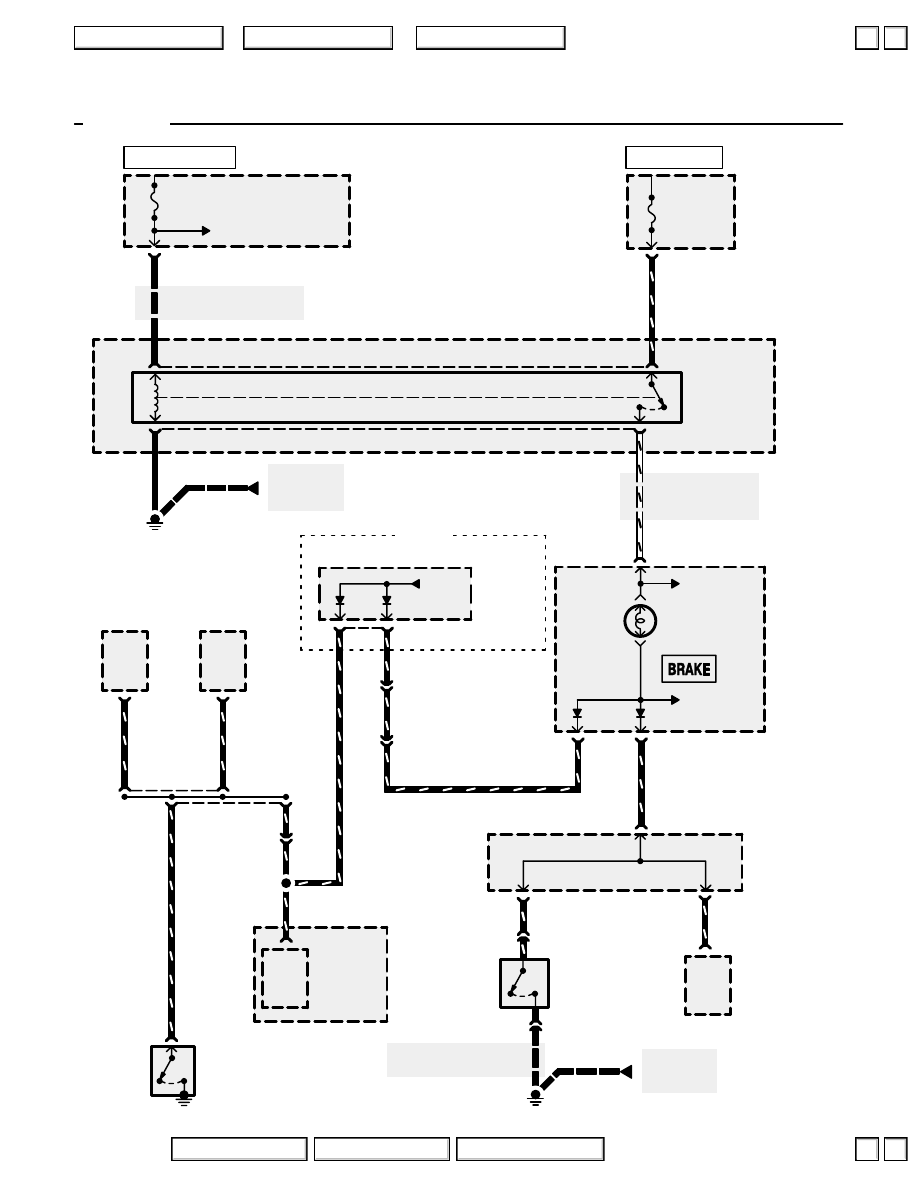
Brake System Indicator Light
See Ground Distribution,
page 14-7.
See Gauge
Assembly,
page 80-5 or 80-9.
YEL
YEL
See Ground
Distribution,
page 14-6.
C331
See Power Distribution,
page 10-10.
GRN/RED
Brake/
park
input
(PARK)
VSA
MODULATOR/
CONTROL
UNIT
UNDER-HOOD
FUSE/RELAY
BOX
GAUGE
ASSEMBLY
PHOTO 71
(’00-’03)
PHOTO 212
VIEW 113
See Power Distribution,
page 10-10.
PARKING
BRAKE SWITCH
Closed with parking
brake applied.
C307
1
2
RED/YEL
17
GRN/
RED
11
UNDER-DASH
FUSE/RELAY
BOX
A
C502
GRN/RED
G301
C321
GRN/WHT
C322
BRAKE FLUID
LEVEL SWITCH
Closed with low
fluid level.
See Ground
Distribution,
page 14-7.
See Gauge
Assembly
14
C331
BLK
METER
7.5A
METER
15A
’00-’04
GAUGE
RELAY
3
1
5
2
UNDER-
HOOD
RELAY
BOX C
GRN/WHT
1
C405
GRN/
RED
Brake/
park
input
IMMOBILIZER
CONTROL
UNIT
7
A
38
UNDER-DASH
FUSE/RELAY
BOX
WHT/RED
WHT/RED
22
A
G301
BLK
GRN/RED
BLK
BLK
GRN/RED
Brake/
park
input
DRIVER’S
MULTIPLEX
CONTROL
UNIT
16
C
C421
(Terminals
17-20)
UNDER-
DASH
FUSE/
RELAY
BOX
See Gauge
Assembly
GRN/RED
See
Head-
lights
C414
2
DAYTIME
RUNNING
LIGHTS
CONTROL
UNIT
6
13
GRN/RED
C409
10
GRN/
RED
5
GRN/RED
B
C504
3
GRN/
RED
GRN/
RED
36
VSA
MODULATOR/
CONTROL
UNIT
Canada
GRN/RED
(BFL)
HOT IN ON OR START
HOT AT ALL TIMES
BRAKE
SYSTEM
INDICATOR
LIGHT
*
*
= ’04 indicators are LEDs
2004 American Honda Motor Co., Inc.
▼
▼
+
–
71-3
Brake System Indicator Light
How the Circuit Works
The brake system indicator light comes on to
alert the driver that the parking brake is applied,
or that the brake fluid level is low. It also comes
on as a bulb test when the engine is cranked.
Parking Brake
With the ignition switch in ON (II) or START (III),
voltage is applied through fuse 13 to the gauge
relay. The gauge relay then applies battery
voltage through fuse 55 to the brake system
indicator light. When you apply the parking brake,
the switch closes and provides a ground for the
light, and the light comes on to remind the driver
that the parking brake is applied.
Brake Fluid Level
The brake system indicator receives battery
voltage through fuse 55 and the gauge relay. If
the brake fluid level is low, the brake fluid level
switch closes, providing ground to the circuit. The
brake system indicator light then comes on,
alerting the driver to a low brake fluid level in the
master cylinder. (Check brake pad wear before
adding fluid.)
Bulb Check
With the ignition switch in ON (ll) and the engine
not running, the alternator applies a ground signal
to the WHT/BLU wire to turn on the brake system
indicator light as a bulb check.
Refer to the Service Manual (Section 23, Electrical)
for specific tests or troubleshooting procedures.
2004 American Honda Motor Co., Inc.
▲
▼
▲
▼
72
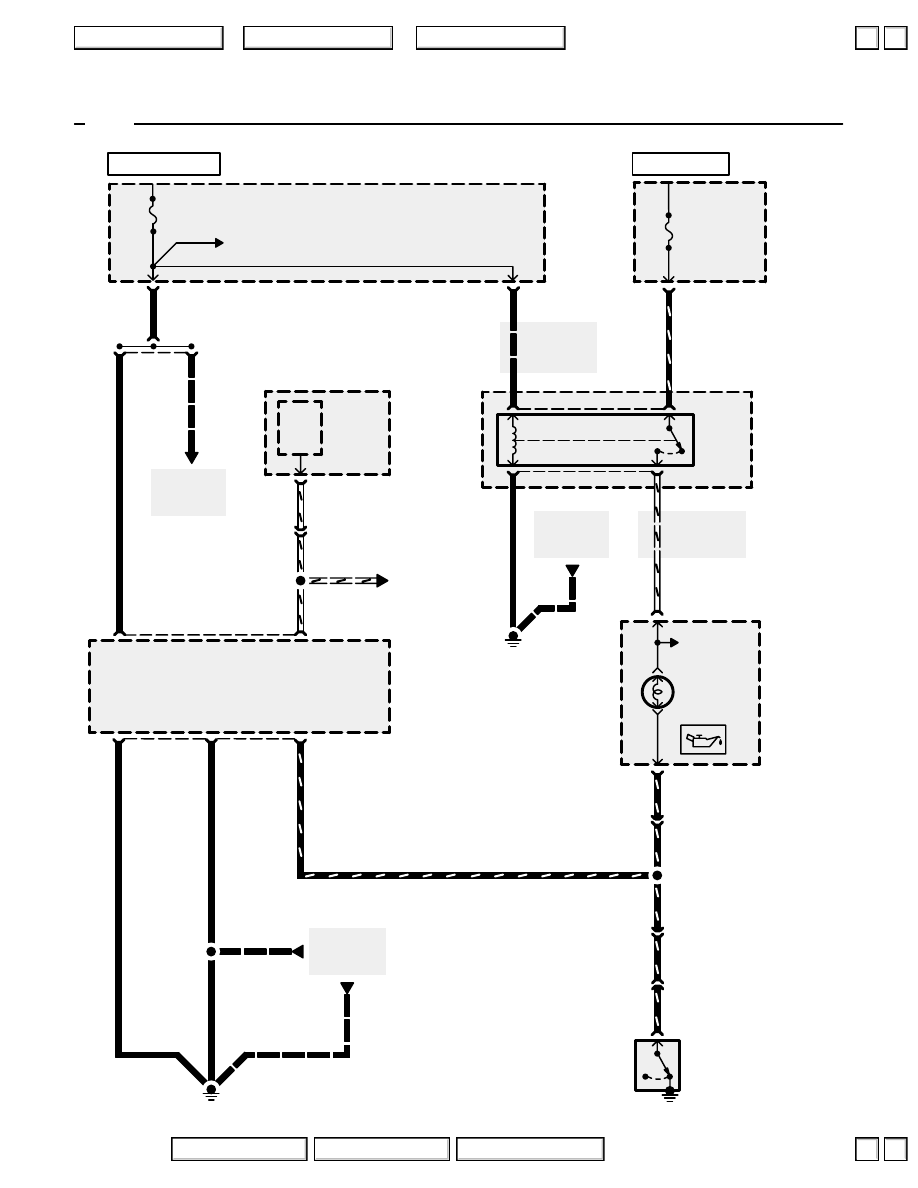
Engine Oil Pressure Indicator Light
See Ground
Distribution,
page 14-12.
BLK
18
ENGINE OIL
PRESSURE
SWITCH
Closed with low
oil pressure
UNDER-
DASH
FUSE/
RELAY
BOX
PASSENGER’S
MULTIPLEX
CONTROL
UNIT
Voltage
Regulator
ALTERNATOR
See Gauge
Assembly
LOW
ENGINE OIL
PRESSURE
INDICATOR
LIGHT
GAUGE
ASSEMBLY
L
A
2
C104
C123
A
3
C476
6
WHT/BLU
WHT/BLU
WHT/BLU
3
1
20
1
METER
7.5A
G402
BLK
YEL/RED
YEL/RED
YEL/RED
YEL/RED
See Power
Distributon,
page 10-10.
C404
8
YEL
YEL
See Power
Distributon,
page 10-10.
14
3
BLK
A
C102
3
YEL/RED
See Gauge
Assembly,
page 80.
See Power
Distribution,
page 10-10.
UNDER-
HOOD
FUSE/
RELAY
BOX
C331
2
C307
1
3
See Ground
Distribution,
page 14-6.
G301
5
BLK
1
WHT/RED
A
22
GAUGE
RELAY
UNDER-
HOOD
RELAY
BOX C
2
RED/YEL
YEL
YEL
WHT/RED
METER
15A
YEL/RED
C448
(Terminals 14-16)
Ignition
input
Engine
running
input
Engine oil pressure
switch input
Ground
Ground
’96
HOT IN ON OR START
HOT AT ALL TIMES
2004 American Honda Motor Co., Inc.
▲
▲
+
–
72-1
Engine Oil Pressure Indicator Light
18
ENGINE OIL
PRESSURE
SWITCH
Closed with low
oil pressure
UNDER-
DASH
FUSE/
RELAY
BOX
PASSENGER’S
MULTIPLEX
CONTROL
UNIT
Voltage
Regulator
ALTERNATOR
See Gauge
Assembly
LOW
ENGINE OIL
PRESSURE
INDICATOR
LIGHT
GAUGE
ASSEMBLY
L
A
2
C104
C123
A
3
C476
6
WHT/BLU
WHT/BLU
WHT/BLU
3
1
20
1
METER (’97-’98)
METER
SUN ROOF (’99-’03)
7.5A
G402
BLK
See Ground
Distribution,
page 14-12.
YEL/RED
YEL/RED
YEL/RED
YEL/RED
See Power
Distributon,
page 10-10.
C404
8
YEL
YEL
See Power
Distributon,
page 10-10.
14
3
BLK
A
C102
3
YEL/RED
C502
1
A
11
BLK/YEL
ECU
20A
YEL/RED
BLK
C448
(Terminals 14-16)
Ignition
input
Engine
running
input
Engine oil pressure
switch input
Ground
Ground
’97-’03
See Power
Distributon,
page 10-8.
See Power
Distributon,
page 10-9.
BLK/YEL
HOT IN ON OR START
HOT IN ON OR START
2004 American Honda Motor Co., Inc.
Нет комментариевНе стесняйтесь поделиться с нами вашим ценным мнением.
Текст