Mazda Automatic Transaxle JA5A-EL. Manual — part 32

AUTOMATIC TRANSAXLE
K133
K1
2-4 BRAKE, LOW AND REVERSE BRAKE DISASSEMBLY
AME571419091A02
1. Disassemble in the order indicated in the table.
.
AMU0517A085
1
Snap ring
2
Driven plate
3
Drive plate
4
Retaining plates
5
Snap ring
K134 Snap Ring Disassembly Note
6
Piston and retainer
7
Return spring
8
Spring retainer
9
Dished plate
10
Retaining plate
11
Driven plate
12
Drive plate
13
Retaining plate
14
Snap ring
15
One-way clutch
16
2-4 brake piston
(See

K134
AUTOMATIC TRANSAXLE
Snap Ring Disassembly Note
Caution
•••• Depress the spring retainer only enough to remove the snap ring. Overpressing will damage the
retainer assembly edges.
1. Install the SSTs in the transaxle case as shown in
the figure.
2. Remove the snap ring.
3. Remove the SSTs.
2-4 Brake Piston Disassembly Note
Warning
•••• Using compressed air can cause dirt and other particles to fly out, causing injury to the eyes.
Wear protective eye wear whenever using compressed air.
1. Using an air gun, blow air into circuit to blow out
the 2-4 brake piston as shown in the figure.
2. Remove the seal ring and O-ring from the 2-4
brake piston.
End Of Sie
2-4 BRAKE, LOW AND REVERSE BRAKE INSPECTION
AME571419091A03
Drive Plate Inspection
1. Measure the facing thickness in three places, and determine the average of the three readings.
• If not within the specification, replace the drive plates.
Thickness
Minimum: 1.7 mm {0.067 in}
Spring and Retainer Inspection
1. Measure the free length of each spring and inspect for deformation.
• If not within the specifications, replace the spring and retainer.
AMU0517A167
AMU0517A086

AUTOMATIC TRANSAXLE
K135
K1
Specification
2-4 brake return spring
Low and reverse return spring
End Of Sie
2-4 BRAKE, LOW AND REVERSE BRAKE ASSEMBLY
AME571419091A04
Assembly Procedure
1. Apply a coat of ATF to a new seal ring and new
O-ring, then install them to the 2-4 brake piston.
Note
• After installing the piston, ensure that piston
rotates smoothly by hand. If not, the lip seal
may be caught.
Low and reverse brake
1. Measure the snap ring groove width A.
2. Measure the snap ring thickness B.
3. Calculate the clearance using the following
formula.
Clearance = A B
0.0 0.2 mm {0.000 0.008 in}
4. If the clearance is out of specification, select a
suitable snap ring.
Selectable snap ring thickness
mm {in}
Note
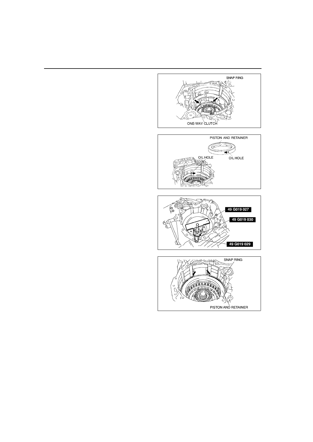
• The low one-way clutch must be installed with the groove facing upward.
5. Install the low one-way clutch.
Note
• The snap ring opening must be positioned
as shown in the figure.
Outer
diameter
(mm {in})
Free length
(mm {in})
No. of
coils
Wire diameter
(mm {in})
8 {0.31}
21.4 {0.84}
6.6
1.0 {0.039}
Outer
diameter
(mm {in})
Free length
(mm {in})
No. of
coils
Wire thickness x
wire width
(mm {in})
178.9 {7.04}
20.3 {0.79}
4
1.3 x 5.2
{0.05 x 0.20}
AMU0517A087
2.1 {0.083}
2.2 {0.087}
2.3 {0.091}
AMU0517A088
AMU0517A089
K136
AUTOMATIC TRANSAXLE
6. Install the snap ring.
7. Install the retaining plates, drive plates, driven
plates, dished plate, and spring retainer.
8. Install the return spring.
Note
• When installing the piston and retainer, align
the oil holes as shown in the figure.
9. Install the piston and retainer.
Caution
•••• Depress the spring retainer only enough
to remove the snap ring. Overpressing
will damage the retainer assembly edges.
10. Install the SSTs in the transaxle case as shown in
the figure.
Note
• The snap ring opening must be positioned
as shown in the figure.
11. Install the snap ring.
Note
• The snap ring opening must be positioned
as shown in the figure.
AMU0517A044
AMU0517A090
AMU0517A167
AMU0517A091
Нет комментариевНе стесняйтесь поделиться с нами вашим ценным мнением.
Текст