Mazda Training manual — part 88
Dynamic Driving Safety Systems
ABS
Pressure Increase Mode
•
When the CM detects that the wheel slip decreases below a specified value, it increases
the brake force to that wheel, in order to keep the wheel slip in the specified range.
•
It deactivates the inlet and outlet solenoid valve and the pump. Thus, the pressure
increase is performed in the same way as during normal braking, the brake pressure is
increased by the driver’s foot, still pressing the brake pedal.
Inlet solenoid valve
Outlet solenoid valve
Pump motor
OFF (open)
OFF (closed)
OFF (stopped)
L2003_T02004
•
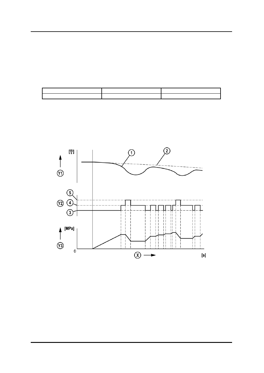
These three modes are repeated as required until either: the brake pedal is released,
the speed of the vehicle is below the specified value for ABS operation (approx. 5...15
km/h, depending on the vehicle) or the wheel slip does not exceed the specified value
anymore.
L2003_02008
X Time
2 Calculated
vehicle
speed
Y1 Speed
3 Pressure
increase
Y2
Solenoid valve control
4
Pressure hold
Y3
Brake fluid pressure
5
Pressure reduction
1 Wheel
speed
Curriculum Training
02-11
ABS
Dynamic Driving Safety Systems
Servicing
•
The ABS HU contains delicate mechanical parts. If foreign materials get into the
component the ABS may fail to operate. Also, it will likely become extremely difficult to
find the location of the malfunction in the event that the brakes operate but the ABS
does not. Make sure foreign materials do not get inside when servicing the ABS (e.g.
brake fluid replacement, pipe removal).
•
To avoid trouble coming from the hydraulic system of the ABS and the brake it is best to
protect the whole system with a regular exchange of brake fluid and flushing of the
hydraulic ABS unit.
NOTE: To avoid that the HU runs dry and air enters the HU, always install apropriate
closing covers when removing hydraulic lines.
Bleeding
NOTE: In most cases it is not necessary to bleed the HU with the aid of the M-MDS during
exchange of the brake fluid. Always follow the procedure of the corresponding W/M
(Workshop Manual).
•
If the ABS HU needs to be flushed or bled, it is necessary to switch on the pump and the
outlet valves.
NOTE: Always perform the manual bleeding procedure before performing any bleeding
procedure with the aid of the M-MDS
•
Connect the brake-bleeding device with the brake fluid reservoir ensuring that fresh
brake fluid will get to the HU.
•
For Mazda2 and Tribute the M-MDS provides the “ABS Service Bleed” function.
Connect the M-MDS with DLC2 and select
Æ 16PINDLC Æ Toolbox Æ Chassis Æ
Braking
Æ ABS Service Bleed and follow the screen instructions
02-12 Curriculum
Training
Dynamic Driving Safety Systems
ABS
•
For models the M-MDS does not provide a service bleed function, ABS valves and the
ABS pump can be activated via the Simulation Test Mode available in the DataLlogger
menu. Connect the M-MDS and select
Æ Toolbox Æ Datalogger Æ Modules Æ ABS
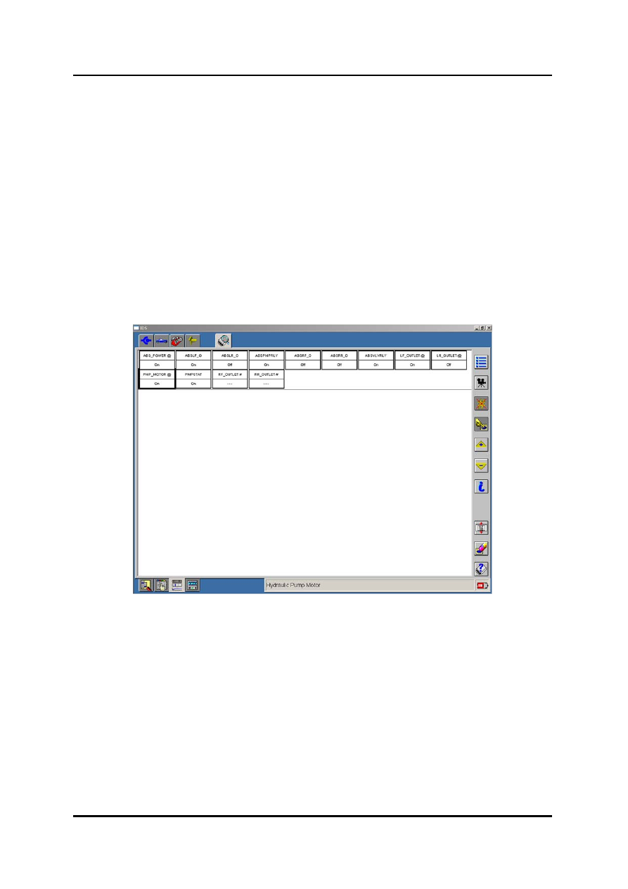
•
Then select PIDs as displayed below.
•
To start the activation of the valve and the pump in the HU:
–
Select and activate
Æ ABS_POWER
–
Select and activate the outlet solenoid valve of the corresponding brake calliper a
bleeding bottle is connected with (here it is the left front side)
Æ LF_OUTLET and
PMP_MOTOR
NOTE: To prevent the ABS unit from overload, the solenoid valves and pump motor must
not be activated permanently when bleeding. Depending on the model, the pump
motor and the solenoid valves are either automtically deactivated 10 seconds after
beeing activated with the aid of the M-MDS or they must be deactivated manually.
L2003_02052
•
Repeat the procedure for each outlet valve.
Curriculum Training
02-13

ABS
Dynamic Driving Safety Systems
Diagnostics
•
The HU/CM can be checked by:
–
Reading out DTCs
–
Checking voltage signals
–
Monitoring / Activating the corresponding PIDs (see below)
NOTE: The ABS warning light might stay illuminated after deleting DTCs, until the unit
performed a self test. Therefore it is necessary to perform a test drive after deleting
DTCs.
PID
Definition Unit/Condition
BOO_ABS
Brake switch
ON/OFF
CCNTABS
Number of detected DTCs
-
LR_OUTLET#
LR ABS pressure outlet solenoid valve
ON/OFF
LR_INLET#
LR ABS pressure inlet solenoid valve
ON/OFF
LR_WSPD
LR ABS wheel-speed sensor input
km/h, mph
RR_INLET#
RR ABS pressure inlet solenoid valve
ON/OFF
RR_OUTLET#
RR ABS pressure outlet solenoid valve
ON/OFF
RR_WSPD
RR ABS wheel-speed senosr input
km/h, mph
LF_INLET#
LF ABS pressure inlet solenoid valve
ON/OFF
LF_OUTLET#
LF ABS pressure outlet solenoid valve
ON/OFF
LF_WSPD
LF ABS wheel-speed sensor input
km/h, mph
RF_INLET#
RF ABS pressure inlet solenoid valve
ON/OFF
RF_OUTLET#
RF ABS pressure outlet solenoid valve
ON/OFF
RF_WSPD
RF ABS wheel-speed sensor input
km/h, mph
PMP_MOTOR#
ABS motor
ON/OFF
L2003_T02006
NOTE: Depending on the model, the availability of the PIDs varies. In addition, different PID
names may be used for identical parameters (see W/M).
Replacement
•
A new HU is usually delivered pre filled. Nevertheless, the brake system must be bled
according to the W/M.
•
A new CM must be configured (except for Mazda2 (DY) and B-Series (UN)) with the aid
of the M-MDS, via the option “Programmable Module Installation” (refer to W/M). If a
new DSC HU/CM has been installed, additional initialisation procedures of the sensors
must be performed (refer to W/M).
02-14 Curriculum
Training
Нет комментариевНе стесняйтесь поделиться с нами вашим ценным мнением.
Текст