Mazda Training manual — part 101

Dynamic Driving Safety Systems
DSC
Diagnostics
•
The HU/CM can be checked by:
–
Reading out DTCs
–
Checking voltage signals
–
Monitoring / Activating the corresponding PIDs (see below)
PID
Definition Unit/Condition
BOO_ABS
Brake switch
ON/OFF
CCNTABS
Number of detected DTCs
-
ESP_VOLT
IVD/DSC sensor supply voltage
V
LATACCEL#
Initialisation start-up for combined sensor
True / False
LAT_ACCL
Lateral G-force from combined sensor
G
LF_INLET#
LF ABS pressure inlet solenoid valve
ON/OFF
LF_OUTLET#
LF ABS pressure outlet solenoid valve
ON/OFF
LF_TC_PRV#
LF stability control solenoid valve
ON/OFF
LF_TC_SWV#
LF traction control solenoid valve
ON/OFF
LF_WSPD
LF ABS wheel-speed sensor input
km/h, mph
LR_INLET#
LR ABS pressure inlet solenoid valve
ON/OFF
LR_OUTLET#
LR ABS pressure outlet solenoid valve
ON/OFF
LR_WSPD
LR ABS wheel-speed senor input
km/h, mph
MCYL_S_CAL#
Initialisation start-up for brake fluid pressure sensor
True / False
MPREDTDR
Brake fluid pressure
kPa, psi, bar
PMP_MOTOR#
ABS motor
ON/OFF
RF_INLET#
RF ABS pressure inlet solenoid valve
ON/OFF
RF_OUTLET#
RF ABS pressure outlet solenoid valve
ON/OFF
RF_TC_PRV#
RF stability control solenoid valve
ON/OFF
RF_TC_SWV#
RF traction control solenoid valve
ON/OFF
RR_INLET#
RR ABS pressure inlet solenoid valve
ON/OFF
RR_OUTLET#
RR ABS pressure outlet solenoid valve
ON/OFF
RF_WSPD
RF ABS wheel-speed sensor input
km/h, mph
RR_WSPD
RR ABS wheel-speed sensor input
km/h, mph
SWA_POS
Steering angle sensor
°
TCYC_FS
DSC stand by
ON/OFF
TCYC_SW
DSC OFF switch
Pressed/Not pressed
YAW_RATE
Yaw rate value from combined sensor
°/s
L2003_T02019
Mazda3
Curriculum Training
02-63
DSC
Dynamic Driving Safety Systems
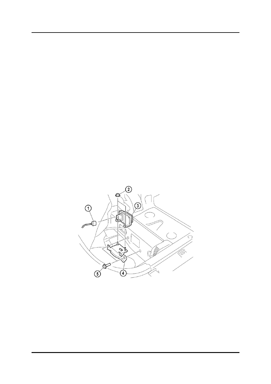
Combined Sensor
•
On current Mazda vehicles, the combined sensor is located either below the passenger’s
seat, or below the centre console (MX-5 and Mazda6). As the name implies, it
incorporates a combination of at least two sensors, that measure yaw rate and
transverse acceleration.
•
The combined sensor is either hardwired or connected via a separate CAN to the DSC
HU/CM.
•
The sensors themselves are a special kind of accelerometer built into a microchip (or a
similar type). They operate both mechanically and/or electronically and are used to
detect yaw rate and lateral G force acting on the vehicle. The combined sensor transmits
detected forces either via CAN to the DSC CM or, if hardwired, as a corresponding
voltage signal. These signals are used to assist the DSC CM to distinguish between
stable and unstable driving conditions.
NOTE: The combined sensor is highly sensitive against impacts. Therefore, the sensor has
to be replaced after it fell down.
NOTE: The mounting bolts and nuts of the combined sensor must always be tightened to the
specified torque in the compulsory sequence (refer to W/M). Ensure that the sensor
is correctly aligned, otherwise the measurement results for yaw rate and transverse
acceleration could be affected, causing a malfunction of the DSC.
L2003_02037
1 Combined
sensor
connector
4 Bracket
2 Nut
5 Bolt
3 Combined
sensor
02-64 Curriculum
Training

Dynamic Driving Safety Systems
DSC
Diagnostics
•
The combined sensor can be checked by:
–
Reading out DTCs
–
Checking voltage signals
–
Monitoring / Activating the corresponding PIDs (see below)
PID
Definition Unit/Condition
LATACCEL#
Initalisation start-up for combined sensor
ON/OFF
LAT_ACCL
Lateral G-force from combined sensor
G
YAW_RATE
Yaw rate value from combined sensor
°/s
L2003_T02025
Replacement
•
If a combined sensor needs to be replaced, the new sensor must be initialised with the
aid of the M-MDS (refer to W/M).
Steering Angle Sensor
•
The steering angle sensor is attached to the steering column, and is located between the
clock spring and the combination switch. It is either integrated into the combination
switch or is a separate component.
•
Mazda vehicles are equipped with different types of combination sensors. They always
transmit a steering wheel turn signal allowing the DSC CM to detect any rotation
(degrees and direction) and the neutral position of the steering wheel. The steering angle
sensor is either hardwired or connected via HS-CAN to the DSC HU/CM. Up to three
different voltage signals can be transmitted from a hardwired steering angle sensor,
depending on the model.
•
Signal generation is done either with the aid of a photoelectric barrier, hall element type
sensors, or GMR (Giant Magneto Resistor) type sensors. The operation of the
photoelectric barrier type is explained below.
•
The steering angle sensor on the Mazda3 (BK) is a separate unit. It features a sensor
unit with a photo transistor, positioned opposite a LED straddling a slitted disc, that
rotates together with the steering wheel.
•
As the disc rotates, the LED light, received by the photo transistor, varies due to the slits
on the disc. The photo transistor outputs an ON signal when it receives light and an OFF
signal when the light is blocked. The DSC HU/CM calculates the steering angle and the
turning speed of the steering wheel based on the phase difference between sensor A
and B outputs.
Curriculum Training
02-65

DSC
Dynamic Driving Safety Systems
L2003_02038
1
Vehicle front
5
Steering angle signal A
2
Disc
6
Detection circuit (inside DSC HU/CM)
3 Sensor
unit
7 Slit
4
Steering angle signal B
02-66 Curriculum
Training
Нет комментариевНе стесняйтесь поделиться с нами вашим ценным мнением.
Текст