Mazda Training manual — part 20

Powertrain Engines
Valve Train
•
The camshaft is driven by a timing belt, which has to be replaced every 120,000 km.
L1001.4_01066
1
Camshaft pulley
7
Crankshaft pulley
2
Camshaft
8
Timing belt tensioner
3
Rocker arm
9
Tensioner pulley
4
Rocker bridge
10
Water pump pulley
5
Fuel high-pressure pump pulley
11
Timing belt
6 Idler
pulley
Curriculum Training
01-67
Engines Powertrain
Timing Belt Tensioner
•
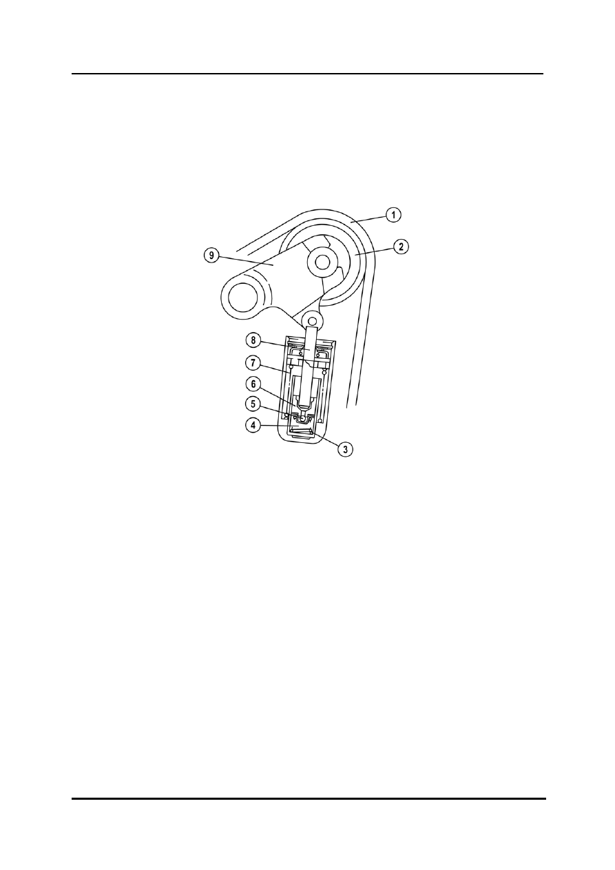
An automatic timing belt tensioner is fitted to ensure optimum belt tension over the
service life of the engine.
•
The timing chain tensioner operates using a hydraulic mechanism, which also
compensates the increased belt tension due to heat expansion of the engine
components.
L1001.4_01120
1 Timing
belt
6 Plunger
2 Tensioner
pulley
7 Spring
3
Plunger spring
8
Tensioner rod
4
Pressure chamber
9
Tensioner arm
5 Check
valve
01-68 Curriculum
Training
Powertrain Engines
•
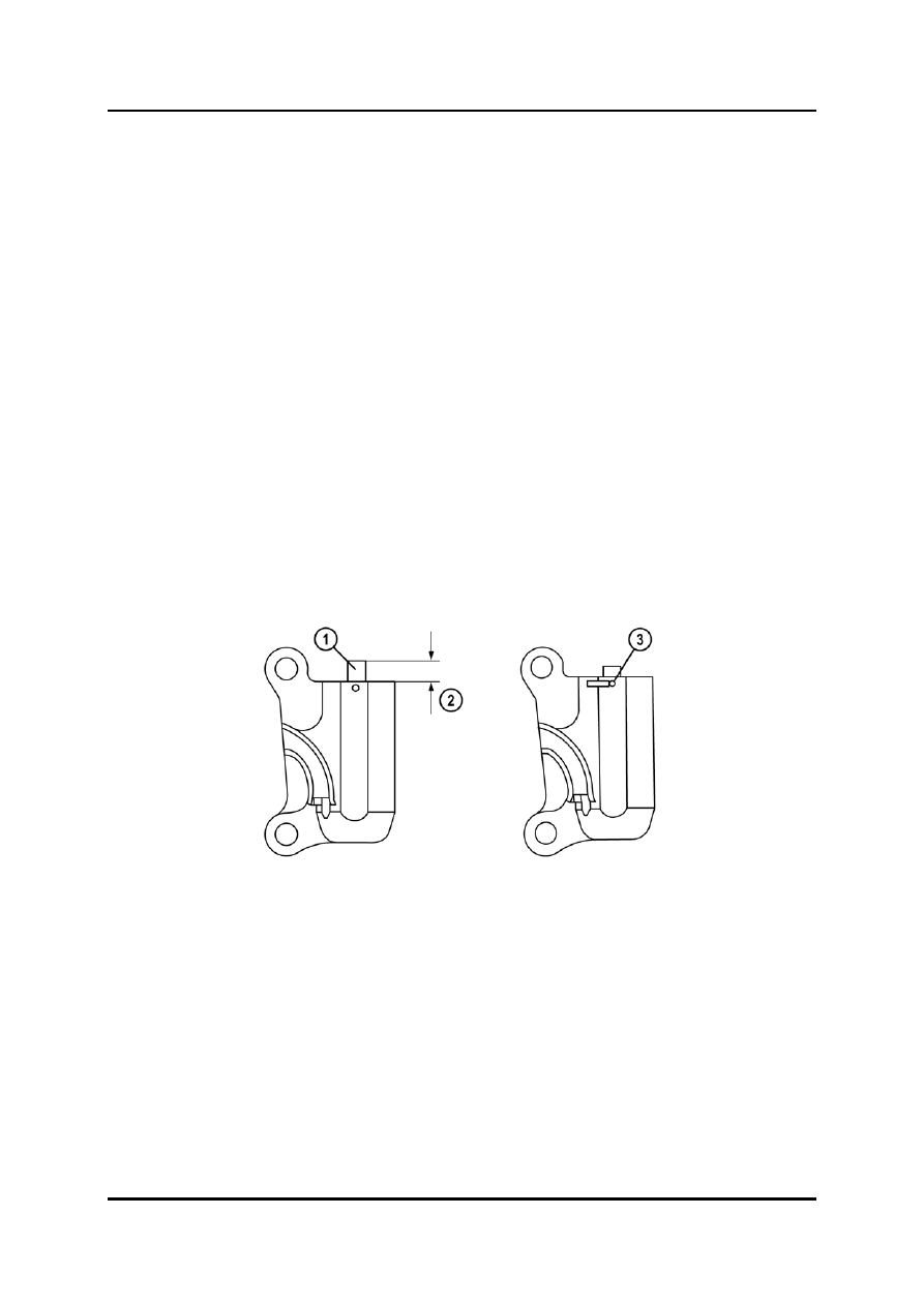
When replacing the timing belt, the timing belt tensioner has to be checked as following
(refer to the workshop manual for details):
–
Measure the tensioner rod projection length.
–
Inspect the tensioner for oil leakage.
–
Verify the thrust/resistance of the tensioner.
NOTE: If the tensioner rod projection length and/or tensioner thrust/resistance exceeds the
specification and/or there is an oil leakage, replace the timing belt tensioner.
•
Before installing the timing belt tensioner, the tensioner rod has to be pushed down and
secured by inserting a locking pin with 1.5 mm diameter (refer to the workshop manual
for details).
NOTE: Placing the timing belt tensioner horizontally while pushing the tensioner rod can
cause oil leakage and damage the automatic tensioner.
NOTE: To prevent damage to the timing belt tensioner, the tensioner rod has to be pushed
slowly with a force not greater than the specified 235 N. The tensioner rod must not
touch the bottom.
L1001.4_01067
1
Tensioner rod
3
Locking pin
2
Tensioner rod projection length
Curriculum Training
01-69

Engines Powertrain
Valve Timing
•
For verifying or adjusting the valve timing the timing marks have to be aligned as shown
below (refer to the workshop manual for details).
•
Before installing the timing belt the camshaft pulley must be fixed to the cylinder head
using a bolt (M8 x 1.25). In addition, the fuel high-pressure pump pulley has to be locked
against rotation with the aid of the FIP (Fuel Injection Pump) repair kit (part no. RFY1-13-
SMO).
NOTE: In order to prevent damage to the camshaft pulley, the detent bolts do not have to be
fully tightened.
L1001.4_01068
1
Timing mark (camshaft pulley)
4
Timing mark (crankshaft pulley)
2
Timing mark (fuel high-pressure pump
pulley)
5
Hole for detent bolt
3 FIP
repair
kit
01-70 Curriculum
Training
Нет комментариевНе стесняйтесь поделиться с нами вашим ценным мнением.
Текст