Mazda Training manual — part 27
Powertrain Engines
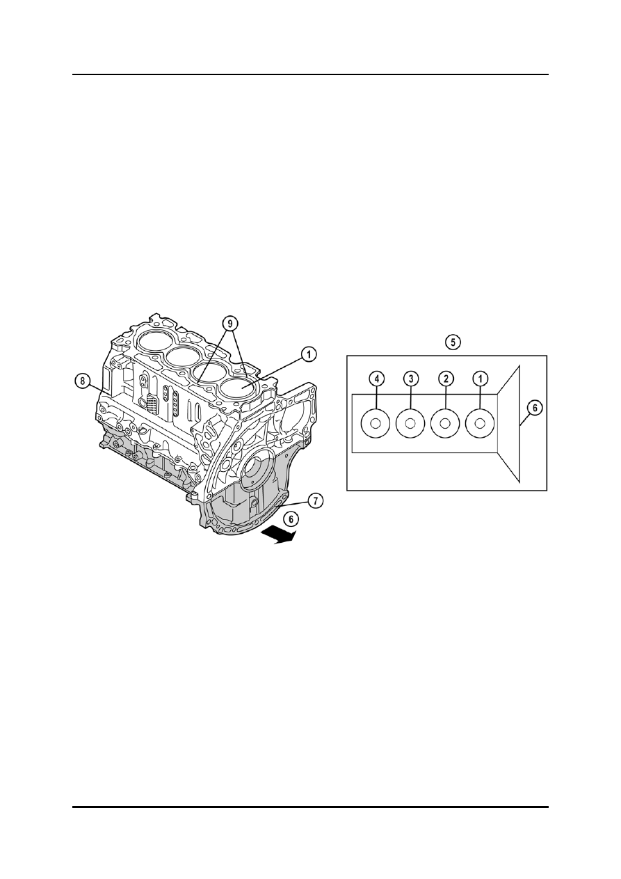
Cylinder Block
•
The cylinder block is equipped with cylinder liners, the coolant jackets of which are open
towards the top.
•
The cylinder block is composed of an upper and a lower cylinder block, in which the
main bearing caps are integrated. Upper and lower cylinder block are matched to each
other, i.e. they cannot be replaced separately. If one of the components exceeds the
specification, the cylinder block must be replaced as a complete unit.
NOTE: Bolt and stud repairs using thread inserts in the area of the cylinder head bolts and
main bearing bolts are not permitted.
•
The cylinder no.1 is located on the transmission side (French-style cylinder numbering).
L1001.4_01087
1
Cylinder no.1
6
Transmission side
2
Cylinder no.2
7
Lower cylinder block
3
Cylinder no.3
8
Upper cylinder block
4
Cylinder no.4
9
Coolant jackets
5
French style cylinder numbering
Curriculum Training
01-95

Engines Powertrain
Pistons
•
The pistons have valve recesses for the intake and exhaust valves.
•
The piston skirt is coated to reduce friction between the piston and the cylinder.
•
The connecting rods are fracture-split on the big end to ensure a perfect fit between
connecting rod and connecting rod bearing cap. For this reason, the pairs of connecting
rods and connecting rod bearing caps must be kept together during removal.
L1001.4_01088
1
Valve recesses
2
Arrow indicating the installation direction
•
There is no positioning tab for locating the lower bearing in the connecting rod big end.
For installing the lower connecting rod bearing shell two alignment tools (SST) are
required (refer to the workshop manual for details).
L1001.4_01144
1
Alignment tools (SST)
01-96 Curriculum
Training
Powertrain Engines
Crankshaft
•
The crankshaft is equipped with a key for the installation of the crankshaft timing pulley
and the crankshaft pulley.
•
The crankshaft timing pulley has a magnetic pulse wheel for the CKP sensor signals.
NOTE: When removing or installing the crankshaft timing pulley care must be taken, since
scratches or impacts can de-magnetize the magnetic pulse wheel.
•
To ensure optimum bearing clearance of the crankshaft, main bearing shells with
different thickness and hence different tolerance class are fitted in one engine. The
upper main bearing shells are only available in one tolerance class and feature a black
color coding on the edge.
•
The lower main bearing shells are available in three different tolerance classes (A, B and
C) and feature one of the following color codings on the edge:
–
Blue (tolerance class A)
–
Black (tolerance class B)
–
Green (tolerance class C)
•
To determine the tolerance class for the lower bearing shell of each main bearing, the
diameter classes of the main bearings and of the main journals have to be verified.
•
The diameter class of the main bearings can be verified by the engraved letters (A to Z)
on the cylinder block, whereas the first letter is equivalent to the diameter class of main
bearing no.5 (the symbol ^ locates the timing belt side).
•
The diameter class of the main journals can be verified by the printed letters (A to Z) on
the crankshaft, whereas the first letter is equivalent to the diameter class of main journal
no.5 (the symbol ^ locates the timing belt side).
Curriculum Training
01-97

Engines Powertrain
L1001.4_01090
1
Diameter classes of the main journals
2
Diameter classes of the main bearings
•
The correct tolerance class for the lower bearing shell of each main bearing can be
determined by the diagram shown below.
L1001.4_01091
1
Diameter class of main journal
4
Black (tolerance class B)
2
Diameter class of main bearing
5
Green (tolerance class C)
3
Blue (tolerance class A)
01-98 Curriculum
Training
Нет комментариевНе стесняйтесь поделиться с нами вашим ценным мнением.
Текст