Mazda Training manual — part 288

AIR CONDITIONING
SG02 - Control System [Manual Air Conditioning]
SG02-3
TC070-15-01H
Control System [Full-auto Air Conditioner]
Tick the components that are equipped with only Full-auto Air Conditioner.
1. Air intake actuator
2. Air mix actuator
3. Airflow mode actuator
4. Blower motor
5. Power MOS FET
6. Magnetic clutch (Z6)
7. Magnetic clutch (LF)
8. Solar radiation sensor
9. Ambient temperature sensor
10. Cabin temperature sensor
11. Evaporator temperature sensor
12. Refrigerant pressure switch
13. Climate control unit
14. A/C relay
15. Blower relay
16. PCM (Z6)
17. PCM (LF)
18. Main fuse block

AIR CONDITIONING
SG02 - Control System [Manual Air Conditioning]
SG02-4
TC070-15-01H
Control System Wiring Diagram [Manual Air Conditioner]
1. Blower relay
2. Blower motor
3. Resistor
4. Air intake actuator
5. Evaporator temperature sensor
6. A/C relay
7. Magnetic clutch
8. Refrigerant pressure switch
9. Main fuse block
10. Fan switch
11. Climate control unit

AIR CONDITIONING
SG02 - Control System [Manual Air Conditioning]
SG02-5
TC070-15-01H
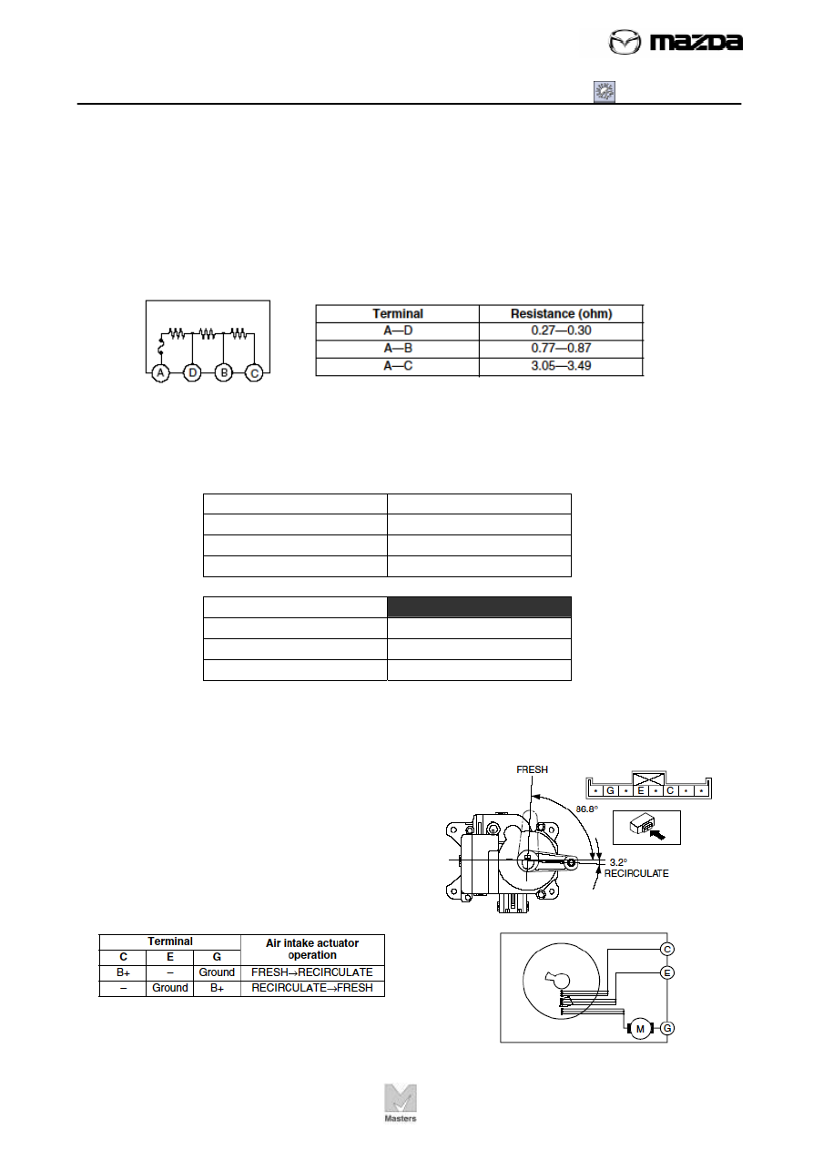
Blower relay
Blower relay is classified as Type B as shown in
the table below. Its function is to be checked by
measuring the continuities.
Type B relay
*
* It requires supplying battery voltage.
Service Tip
Although your multi-meter might have a function to check continuity by giving beep
sounds, use the range of your multi-meter to check resistance (ohm) when you check
continuity between the terminals B and D. This is because your multi-meter may
determine there is a malfunction due to the combined resistance of the resister and
coil between the terminals B and D.
Blower motor
Service Tip
Blower motor can be inspected by directly supplying battery voltage. Connect battery
positive voltage to blower motor terminal A, connect terminal B to ground, and then
verify its operation. It should be operated the same as Fan switch is at its position 4.
AIR CONDITIONING
SG02 - Control System [Manual Air Conditioning]
SG02-6
TC070-15-01H
Resistor
According to the fan switch position, the number of resister connected in series with
the blower motor varies. The voltage applied to the blower motor changes due to the
variation. Look at the table below. The more resistance connected in series with the
blower motor, the less voltage applying to the blower motor, therefore the lower the
revolution of the blower motor.
Provided the measurements are as shown in the table “1”, what do you assume
resistance of each register? (Complete the table “2”)
Table 1
Terminal Resistance
(ohm)
A-D 0.30
A-B 0.80
A-C 3.10
Table 2
Resister
Resistance (ohm)
A-D
D-B
B-C
Air intake actuator
Air intake actuator function can be checked
by directly applying the battery voltage.
Connect battery positive voltage to air intake
actuator terminal C (or G), connect terminal G
(or E) to ground, and verify that the air intake
actuator operates as shown in the table.
Нет комментариевНе стесняйтесь поделиться с нами вашим ценным мнением.
Текст