Mazda CX 7. Manual — part 56

ON-BOARD DIAGNOSTIC [L3 WITH TC]
01-02–179
01-02
Diagnostic procedure
STEP
INSPECTION
ACTION
1
VERIFY FREEZE FRAME DATA HAS BEEN
RECORDED
• Has the FREEZE FRAME DATA been
recorded?
Yes
Go to the next step.
No
Record FREEZE FRAME DATA on the repair order, then go
to the next step.
2
VERIFY RELATED REPAIR INFORMATION
AVAILABILITY
• Check for related Service Bulletins and/or on-
line repair information availability.
• Is any related repair information available?
Yes
Perform the repair or diagnosis according to the available
repair information.
• If the vehicle is not repaired, go to the next step.
No
Go to the next step.
3
CLASSIFY INTERMITTENT CONCERN OR
CONTINUOUS CONCERN
• Clear the DTC from the PCM memory using
the M-MDS.
• Drive the vehicle under the following
conditions:
— Engine coolant temperature is above 63
°C
{145
°F}.
— Engine speed: below 3,750 rpm
— Throttle opening angle is as follows:
• Engine speed below 1,500 rpm: above
35%
• Engine speed between 1,500— 2,500
rpm: between 25— 35%
• Engine speed above 2,500: below 25%
• Is the PENDING CODE for this DTC present?
Yes
Go to the next step.
No
Intermittent concern exists. Go to INTERMITTENT
CONCERN TROUBLESHOOTING procedure.
(See01-03-76 INTERMITTENT CONCERN
TROUBLESHOOTING[L3 WITH TC].)
4
VERIFY IF STORED OTHER DTCs STORED
• Verify stored DTCs using the M-MDS.
• Is DTC P2088 or P2089 present?
Yes
Go to the appropriate DTC troubleshooting procedures.
No
Go to the next step.
5
INSPECT VARIABLE SWIRL SOLENOID VALVE
• Perform “VARIABLE SWIRL SOLENOID
VALVE INSPECTION”.
(See01-13-13 VARIABLE SWIRL SOLENOID
VALVE INSPECTION[L3 WITH TC].)
• Is the variable swirl solenoid valve normal?
Yes
Go to the next step.
No
Replace variable swirl solenoid valve, then go to Step 13.
6
INSPECT VARIABLE SWIRL SHUTTER VALVE
ACTUATOR
• Perform “VARIABLE SWIRL SHUTTER VALVE
ACTUATOR INSPECTION”.
(See01-13-13 VARIABLE SWIRL SHUTTER
VALVE ACTUATOR INSPECTION[L3 WITH
TC].)
• Is the variable swirl shutter valve actuator
normal?
Yes
Go to the next step.
No
Replace the intake manifold, then go to Step 13.
7
INSPECT VARIABLE SWIRL SHUTTER VALVE
SWITCH
• Perform the “VARIABLE SWIRL SHUTTER
VALVE SWITCH INSPECTION”.
(See01-13-13 VARIABLE SWIRL SHUTTER
VALVE ACTUATOR INSPECTION[L3 WITH
TC].)
• Is the variable swirl shutter valve switch
normal?
Yes
Go to the next step.
No
Replace the intake manifold, then go to Step 13.
8
VERIFY CONNECTION OF VACUUM HOSE
ROUTING
• Verify that the vacuum hoses are connected
properly.
• Are the vacuum hoses connected properly?
Yes
Go to the next step.
No
Connect the vacuum hoses properly, then go to the next
step.
1871-1U-06B(01-02).fm 179 ページ 2006年3月15日 水曜日 午前10時32分

ON-BOARD DIAGNOSTIC [L3 WITH TC]
01-02–180
9
INSPECT VARIABLE SWIRL SOLENOID VALVE
OR VARIABLE SWIRL SHUTTER VALVE
SWICTH CONNECTOR FOR POOR
CONNECTION
• Turn the ignition switch to off.
• Disconnect the variable swirl solenoid valve
connector and variable swirl shutter valve
switch connector.
• Inspect for poor connection (such as damaged/
pulled-out pins, corrosion).
• Is there any malfunction?
Yes
Repair or replace the terminal, then go to Step 13.
No
Go to the next step.
10
INSPECT PCM CONNECTOR FOR POOR
CONNECTION
• Turn the ignition switch to off.
• Disconnect the PCM connector.
• Inspect for poor connection (such as damaged/
pulled-out pins, corrosion).
• Is there any malfunction?
Yes
Repair or replace the terminal, then go to Step 13.
No
Go to the next step.
11
INSPECT VARIABLE SWIRL SOLENOID VALVE
OR VARIABLE SWIRL SHUTTER VALVE SW
SIGNAL CIRCUIT FOR OPEN CIRCUIT
• Inspect for continuity between the following
terminals:
— Variable swirl solenoid valve terminal B
(harness-side) and PCM terminal 2AS
(harness-side).
— Variable swirl shutter valve sw terminal A
(harness-side) and PCM terminal 2AE
(harness-side).
• Is there continuity?
Yes
Go to the next step.
No
Repair or replace the wiring harness for an open circuit,
then go to Step 13.
12
INSPECT VARIABLE SWIRL SOLENOID VALVE
OR VARIABLE SWIRL SHUTTER VALVE
SWITCH CIRCUIT FOR SHORT TO POWER
SUPPLY
• Disconnect the variable swirl solenoid valve
connector and variable swirl shutter valve
switch connector.
• Turn ignition switch to the ON position (Engine
off).
• Measure the voltage between the following
terminals and body ground.
— PCM terminal 2AS (harness-side).
— PCM terminal 2AE (harness-side).
• Is the voltage B+?
Yes
Repair or replace the wiring harness for a short to power
supply, then go to the next step.
No
Go to the next step.
13
VERIFY TROUBLESHOOTING OF DTC P2004
COMPLETED
• Make sure to reconnect all disconnected
connectors.
• Start the engine.
• Clear the DTC from the PCM memory using
the M-MDS.
• Start the engine.
• Drive the vehicle under following conditions:
— Engine coolant temperature is above 63
°C
{145
°F}.
— Engine speed: below 3,750 rpm
— Throttle opening angle is as follows
• Engine speed below 1,500 rpm: above
35%
• Engine speed between 1,500— 2,500
rpm: between 25— 35%
• Engine speed above 2,500:below 25%
• Is the PENDING CODE for this DTC present?
Yes
Replace the PCM, then go to the next step.
(See01-40-6 PCM INSPECTION[L3 WITH TC].)
No
Go to the next step.
14
VERIFY AFTER REPAIR PROCEDURE
• Perform the “After Repair Procedure”.
(See01-14-4 AFTER REPAIR
PROCEDURE[L3 WITH TC].)
• Are any DTCs present?
Yes
Go to the applicable DTC inspection.
(See01-02-13 DTC TABLE[L3 WITH TC].)
No
Troubleshooting completed.
STEP
INSPECTION
ACTION
1871-1U-06B(01-02).fm 180 ページ 2006年3月15日 水曜日 午前10時32分
ON-BOARD DIAGNOSTIC [L3 WITH TC]
01-02–181
01-02
End Of Sie
DTC P2006[L3 WITH TC]
id010239810300
DTC P2006
Variable swirl control system shutter valve stuck closed
DETECTION
CONDITION
• PCM monitors the mass variable swirl shutter valve position using the variable swirl shutter valve switch. If
PCM turns the variable swirl solenoid valve off but the variable swirl position still remains closed (variable
swirl shutter valve switch is off), the PCM determines that the variable swirl shutter valve is stuck closed.
Diagnostic support note
• This is a continuous monitor (CCM).
• MIL illuminates if the PCM detects the above malfunction condition in two consecutive drive cycles or in
one drive cycle while the DTC for the same malfunction has been stored in the PCM.
• PENDING CODE is available if the PCM detects the above malfunction condition during the first drive
cycle.
• FREEZE FRAME DATA is available.
• DTCs are stored in PCM memory.
POSSIBLE
CAUSE
• ECT sensor malfunction
• TP sensor malfunction
• CKP sensor malfunction
• Connector or terminal malfunction
• Variable swirl solenoid valve malfunction
• Variable swirl shutter valve malfunction (stuck closed)
• Variable swirl shutter valve actuator malfunction (stuck closed).
• Short to ground circuit between variable swirl solenoid valve terminal B and PCM terminal 2AS
• Short to ground in the wiring harness between variable swirl shutter valve switch terminal A and PCM
terminal 2AE
• PCM malfunction
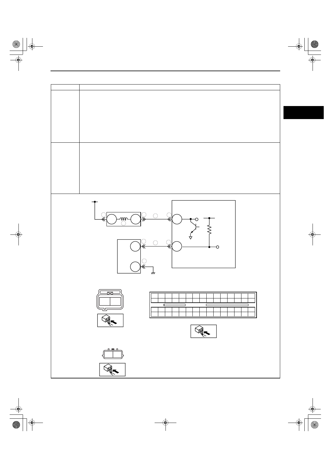
PCM
WIRING HARNESS SIDE CONNECTOR
1BE 1BA 1AW 1AS 1AO 1AK 1AG 1AC 1Y 1U 1Q 1M
1E
1A
1I
1BH 1BD 1AZ 1AV 1AR 1AN 1AJ 1AF 1AB 1X
1T
1P
1H
1D
1L
1BG 1BC 1AY 1AU 1AQ 1AM 1AI 1AE 1AA 1W 1S 1O
1G
1C
1K
1BF 1BB 1AX 1AT 1AP 1AL 1AH 1AD 1Z
1V
1R 1N
1F
1B
1J
B
A
VARIABLE SWIRL SOLENOID VALVE
WIRING HARNESS SIDE CONNECTOR
MAIN RELAY
PCM
7
7
6
9
8
A
B
VARIABLE SWIRL SHUTTER VALVE SWITCH
VARIABLE SWIRL SHUTTER VALVE SWITCH
WIRING HARNESS SIDE CONNECTOR
7
7
8
9
2AS
2AE
VARIABLE SWIRL
SOLENOID VALVE
A
B
A
B
1871-1U-06B(01-02).fm 181 ページ 2006年3月15日 水曜日 午前10時32分

ON-BOARD DIAGNOSTIC [L3 WITH TC]
01-02–182
Diagnostic procedure
STEP
INSPECTION
ACTION
1
VERIFY FREEZE FRAME DATA HAS BEEN
RECORDED
• Has the FREEZE FRAME DATA been
recorded?
Yes
Go to the next step.
No
Record FREEZE FRAME DATA on the repair order, then go
to the next step.
2
VERIFY RELATED REPAIR INFORMATION
AVAILABILITY
• Check for related Service Bulletins and/or on-
line repair information availability.
• Is any related repair information available?
Yes
Perform the repair or diagnosis according to the available
repair information.
• If the vehicle is not repaired, go to the next step.
No
Go to the next step.
3
CLASSIFY INTERMITTENT CONCERN OR
CONTINUOUS CONCERN
• Clear the DTC from the PCM memory using
the M-MDS.
• Drive the vehicle under following conditions:
— Engine coolant temperature is above 63
°C
{145
°F}.
— Engine speed: below 3,750 rpm
— Throttle opening angle is as follows:
• Engine speed below 1,500 rpm: above
35%
• Engine speed between 1,500— 2,500
rpm: between 25— 35%
• Engine speed above 2,500: below 25%
• Is the PENDING CODE for this DTC present?
Yes
Go to the next step.
No
Intermittent concern exists. Go to INTERMITTENT
CONCERN TROUBLESHOOTING procedure.
(See01-03-76 INTERMITTENT CONCERN
TROUBLESHOOTING[L3 WITH TC].)
4
VERIFY STORED OTHER DTCS
• Verify stored DTCs using M-MDS or
equipment.
• Is other DTC present except P0117, P0118,
P0121, P0122, P0123 and/or P0335?
Yes
Go to appropriate DTC troubleshooting procedures.
No
Go to the next step.
5
INSPECT VARIABLE SWIRL SHUTTER VALVE
ACTUATOR
• Perform the “Variable Swirl System Operation
Inspection”.
(See01-03-78 ENGINE CONTROL SYSTEM
OPERATION INSPECTION[L3 WITH TC].)
• Is the variable swirl shutter valve actuator
normal?
Yes
Go to the next step.
No
Replace the variable swirl shutter valve actuator, then go to
Step 10.
6
INSPECT VARIABLE SWIRL SOLENOID VALVE
• Perform the “variable swirl solenoid valve
airflow inspection”.
(See01-13-13 VARIABLE SWIRL SOLENOID
VALVE INSPECTION[L3 WITH TC].)
• Is the variable swirl solenoid valve normal?
Yes
Go to the next step.
No
Replace the variable swirl solenoid valve, then go to Step
10.
7
INSPECT VARIABLE SWIRL SOLENOID VALVE
OR VARIABLE SWIRL SHUTTER VALVE
SWITCH CONNECTOR FOR POOR
CONNECTION
• Turn the ignition switch to off.
• Disconnect the variable swirl solenoid valve
connector and the variable swirl shutter valve
switch connector.
• Inspect for poor connection (such as damaged/
pulled-out pins, corrosion).
• Is there any malfunction?
Yes
Repair the terminal, then go to Step 10.
No
Go to the next step.
8
INSPECT PCM CONNECTOR FOR POOR
CONNECTION
• Inspect for poor connection at the PCM
terminals (such as damaged, pulled-out
terminals, corrosion).
• Is there any malfunction?
Yes
Repair terminal, then go to Step 10.
No
Go to the next step.
1871-1U-06B(01-02).fm 182 ページ 2006年3月15日 水曜日 午前10時32分
Нет комментариевНе стесняйтесь поделиться с нами вашим ценным мнением.
Текст