Mazda CX-9 (2022 year). Manual in english — page 11
When Driving
i-ACTIVSENSE
Do not apply a strong force to an ultrasonic sensor (rear):
When washing the vehicle, do not spray highly pressurized water against an ultrasonic sensor
(rear), or rub it strongly. In addition, do not hit the rear bumper forcefully when loading and
unloading cargo Otherwise, the sensors may not detect obstructions correctly which could
cause the SCBS R system to not operate normally, or it could operate unnecessarily.
CAUTION
¾ When driving off-road in areas where there is grass or foliage, it is recommended that the
SCBS R system be turned off.
¾ Always use tires of the specified size and the same manufacturer, brand, and tread pattern
on all 4 wheels. In addition, do not use tires with significantly different wear patterns on the
same vehicle. Otherwise, the SCBS R system may not operate normally.
¾ If ice or snow is stuck on the ultrasonic sensors (rear) they may not be able to detect
obstructions correctly depending on the conditions. In such cases, the system may not be
able to perform controls correctly. Always drive carefully and pay attention to the rear of
the vehicle.
NOTE
The vehicle posture changes depending on the accelerator pedal, brake pedal and
steering wheel operations, which could make it difficult for the system to recognize an
obstruction, or it could facilitate unnecessary detection. In such cases, the SCBS R may or
may not operate.
The SCBS R system will operate under the following conditions.
The engine is running.
The selector lever is in the R (reverse) position.
“Reverse Smart City Brake Support Malfunction” is not displayed in the
multi-information display.
The vehicle speed is between about 2 to 8 km/h (2 to 4 mph).
The SCBS R is not turned off.
The DSC is not malfunctioning.
The SCBS R operates using ultrasonic sensors (rear) which detect obstructions at the rear
by emitting ultrasonic waves and then receiving the returning waves reflected off the
obstructions.
In the following cases, the ultrasonic sensors (rear) cannot detect obstructions and the
SCBS R may not operate.
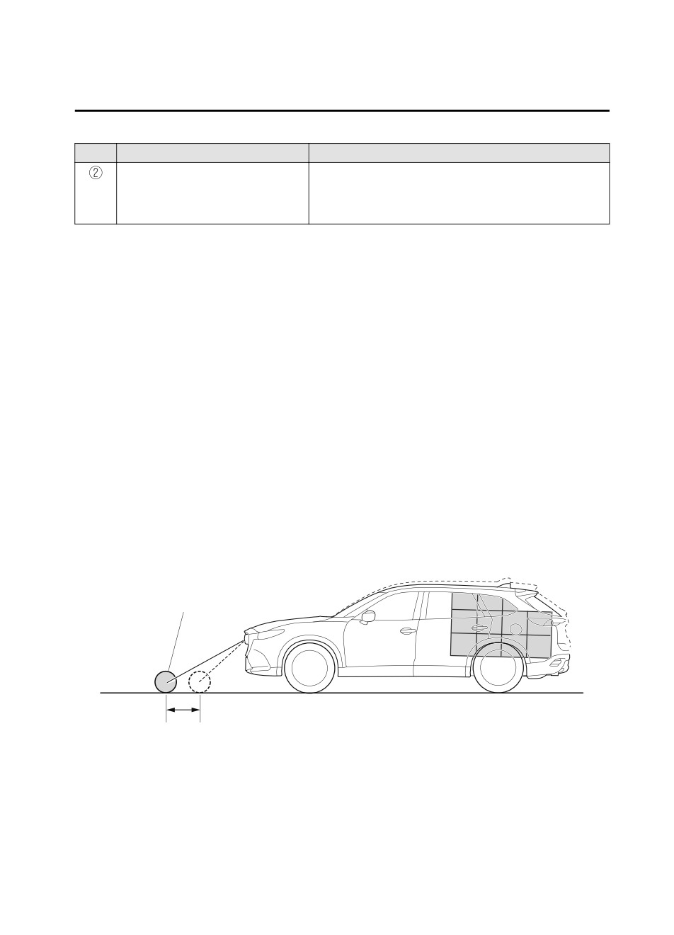
The height of the obstruction is low such as low walls or trucks with low loading
platforms.
The height of the obstruction is high such as trucks with high loading platforms.
4-164
When Driving
i-ACTIVSENSE
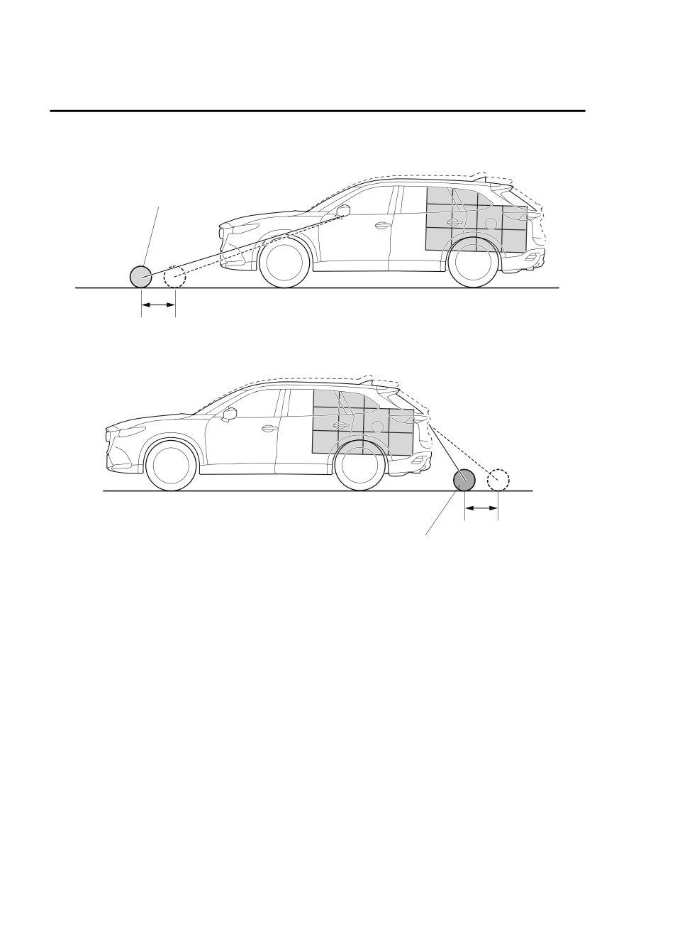
The obstruction is small.
The obstruction is thin such as a signpost.
The obstruction is positioned away from the center of the vehicle.
The surface of the obstruction is not pointed vertically relative to the vehicle.
The obstruction is soft such as a hanging curtain or snow stuck to a vehicle.
The obstruction is shaped irregularly.
The obstruction is extremely close.
In the following cases, the ultrasonic sensors (rear) cannot detect obstructions correctly
and the SCBS R may not operate.
Something is stuck on the bumper near an ultrasonic sensor (rear).
The steering wheel is turned sharply, or the brake or accelerator pedal is operated.
There is another obstruction near one obstruction.
During inclement weather such as rain, fog and snow.
High or low humidity.
High or low temperatures
Strong winds.
The path of travel is not flat.
Heavy luggage is loaded in the luggage compartment or on the rear seat.
Objects such as a wireless antenna, fog light, or illuminated license plate is installed
near an ultrasonic sensor (rear).
The orientation of an ultrasonic sensor (rear) has deviated for reasons such as a
collision.
The vehicle is affected by other sound waves such as the horn, engine noise, ultrasonic
sensor of another vehicle.
In the following cases, an ultrasonic sensor (rear) may detect something as a target
obstruction which could cause the SCBS R system to operate.
Driving on a steep slope.
Wheel blocks.
Hanging curtains, gate poles such as at toll gates and railroad crossing.
When traveling near objects such as foliage, barriers, vehicles, walls, and fences along
a road.
When driving off-road in areas where there is grass and forage.
When passing through low gates, narrow gates, car washing machines, and tunnels.
A towing bar is installed or a trailer is connected.
When the system operates, the user is notified by the multi-information display.
The Smart City Brake Support (SCBS) warning indication (amber) turns on when the
system has a malfunction.
Refer to Taking Action on page 7-36.
4-165
When Driving
i-ACTIVSENSE
▼ Automatic Brake Operation Display
NOTE
When the SCBS R system is set to
The automatic brake operation display is
inoperable, Advanced Smart City Brake
indicated on the multi-information display
Support (Advanced SCBS) and the Smart
after the SCBS R is operated.
Brake Support (SBS) are also set to
inoperable.
NOTE
The collision warning beep sounds
intermittently while the SCBS R brake is
operating.
If the vehicle is stopped by the SCBS R
operation and the brake pedal is not
depressed, the warning beep sounds 1
time after about 2 seconds and the SCBS
R brake is automatically released.
▼ Stopping the Smart City Brake
Support [Reverse] (SCBS R) System
Operation
The SCBS R system can be temporarily
deactivated.
Refer to the Settings section in the Mazda
Connect Owner's Manual.
When the SCBS R system is turned off,
the Smart City Brake Support (SCBS)
OFF indicator light turns on.
When the engine is restarted, the system
becomes operational.
4-166
When Driving
i-ACTIVSENSE
Smart Brake Support
CAUTION
(SBS)*
In the following cases, turn the system off
The SBS system alerts the driver of a
to prevent a mis-operation:
possible collision using a display and
¾ The vehicle is being towed or when
warning sound if the radar sensor (front)
towing another vehicle.
and the Forward Sensing Camera (FSC)
¾ The vehicle is on a chassis roller.
determine that there is the possibility of a
¾ When driving on rough roads such as in
collision with a vehicle ahead while the
areas of dense grass or off-road.
vehicle is being driven at about 15 km/h or
faster (10 mph or faster). Furthermore, if
NOTE
the radar sensor (front) and the Forward
The SBS system operates when all of the
Sensing Camera (FSC) determines that a
following conditions are met:
collision is unavoidable, the automatic
brake control is performed to reduce
The ignition is switched ON.
damage in the event of a collision.
The SBS system is on.
In addition, when the driver depresses the
The vehicle speed is about 15 km/h or
brake pedal, the brakes are applied firmly
faster (10 mph or faster).
and quickly to assist. (Brake Assist (SBS
The relative speed between your
brake assist))
vehicle and the vehicle ahead is about
15 km/h or faster (10 mph or faster).
WARNING
The Dynamic Stability Control (DSC)
is not operating.
Do not rely completely on the SBS system
The SBS system may not operate under
and always drive carefully:
the following conditions:
The SBS is designed to reduce damage in
If the vehicle is accelerated rapidly
the event of a collision, not avoid an
and it comes close to a vehicle ahead.
accident. The ability to detect an
The vehicle is driven at the same
obstruction is limited depending on the
speed as the vehicle ahead.
obstruction, weather conditions, or traffic
The accelerator pedal is depressed.
conditions. Therefore, if the accelerator
The brake pedal is depressed.
pedal or brake pedal is mistakenly
The steering wheel is being operated.
operated it could result in an accident.
The selector lever is being operated.
Always verify the safety of the surrounding
The turn signal is being used.
area and depress the brake pedal or
When the vehicle ahead is not
accelerator pedal while keeping a safer
equipped with taillights or the
distance from vehicles ahead or on-coming
taillights are turned off.
vehicles.
*Some models.
4-167
When Driving
i-ACTIVSENSE
When warnings and messages, such
▼ Collision Warning
as a dirty windshield, related to the
If there is the possibility of a collision with
Forward Sensing Camera (FSC) are
a vehicle ahead, the beep sounds
being displayed in the
continuously and a warning is indicated in
multi-information display.
the multi-information display and the
Although the objects which activate the
active driving display.
system are four-wheeled vehicles, the
radar sensor (front) could detect the
following objects, determine them to be
▼ Stopping The Smart Brake Support
an obstruction, and operate the SBS
(SBS) System Operation
system.
The SBS system can be temporarily
Objects on the road at the entrance to
deactivated.
a curve (including guardrails and
Refer to the Settings section in the Mazda
snow banks).
Connect Owner's Manual.
A vehicle appears in the opposite lane
When the SBS system is turned off, the
while cornering or rounding a curve.
SBS OFF indicator light turns on.
When crossing a narrow bridge.
When passing under a low gate or
through a tunnel or narrow gate.
When entering an underground
parking area.
Metal objects, bumps, or protruding
objects on the road.
If you suddenly come close to a
When the engine is restarted, the system
vehicle ahead.
becomes operational.
When driving in areas where there is
NOTE
high grass or forage.
If the SBS system operation is turned off,
Two-wheeled vehicles such as
the Smart City Brake Support (SCBS)
motorbikes or bicycles.
system operation is turned off
Pedestrians or non-metallic objects
simultaneously.
such as standing trees.
If there is a problem with the SBS
system, a message is displayed in the
multi-information display. Check the
center display to verify the problem and
then have your vehicle inspected by an
Authorized Mazda Dealer.
Refer to Message Indicated on Display
on page 7-41.
4-168
When Driving
i-ACTIVSENSE
360° View Monitor (Mazda Connect (Type A))*
The 360° View Monitor consists of the following functions which assist the driver in
checking the area surrounding the vehicle using various indications in the center display and
a warning sound while the vehicle is being driven at low speeds or while parking.
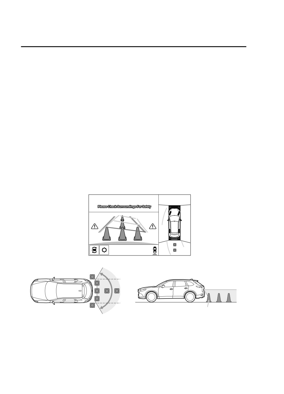
Top view
The top view displays an image of the vehicle from directly above on the center display
by combining the images taken from the 4 cameras set on all sides of the vehicle. The top
view displays on the right side of the screen when the front view or rear view screen is
being displayed. The top view assists the driver in checking the area surrounding the
vehicle when the vehicle is moving forward or in reverse.
Front view/front wide view
The image from the front of the vehicle is displayed on the center display.
The view from the front assists the driver in checking the front of the vehicle by
displaying guide lines on the displayed image taken from the front of the vehicle.
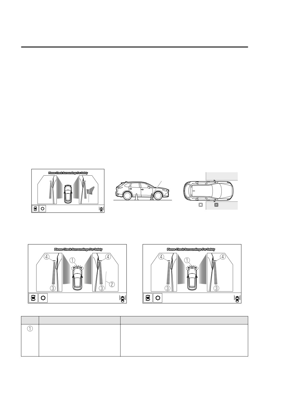
Side view
The images taken from the front left and right sides of the vehicle are displayed on the
center display.
The side view assists the driver in checking the front sides of the vehicle by displaying
guide lines on the displayed image taken from the front left and right sides of the vehicle.
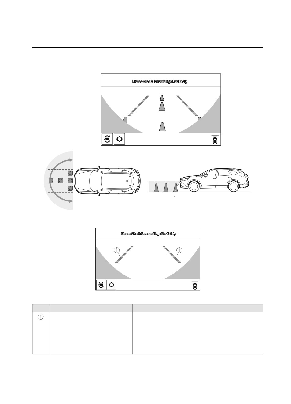
Rear view/rear wide view
The image from the rear of the vehicle is displayed on the center display.
The image from the rear assists the driver in checking the rear of the vehicle by displaying
guide lines on the displayed image taken from the rear of the vehicle.
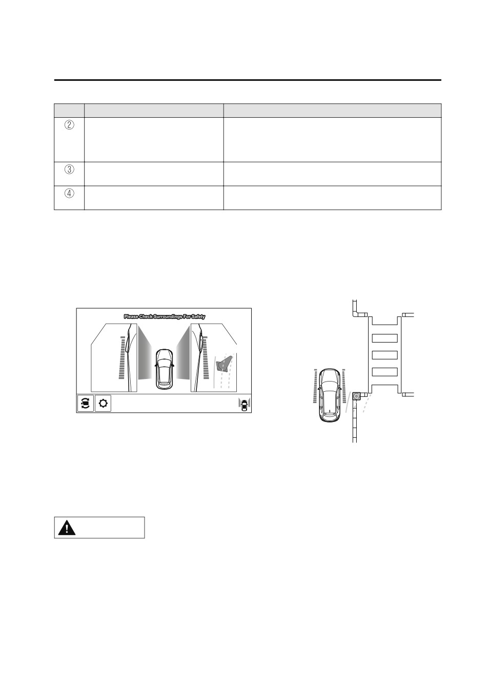
Parking sensor
If there are any obstructions near the vehicle while the top view/side view is displayed, an
obstruction detection indication on the center display turns on.
The parking sensors use ultrasonic sensors to detect obstructions around the vehicle when
the vehicle is driven at low speeds, such as during garage or parallel parking, and notifies
the driver of the approximate distance from the vehicle to the surrounding obstruction
using sound and an obstruction detection indication.
Refer to Parking Sensor System on page 4-260.
Rear Cross Traffic Alert (RCTA)
If there is the possibility of a collision with an approaching vehicle while the rear view/
rear wide view is displayed, a warning is displayed on the center display.
The Rear Cross Traffic Alert (RCTA) uses radar sensors (rear) to detect vehicles
approaching from the rear left and right sides of the vehicle, and it assists the driver in
checking the rear of the vehicle while reversing by flashing the Blind Spot Monitoring
(BSM) warning lights and activating the warning sound.
Refer to Rear Cross Traffic Alert (RCTA) on page 4-127.
*Some models.
4-169
When Driving
i-ACTIVSENSE
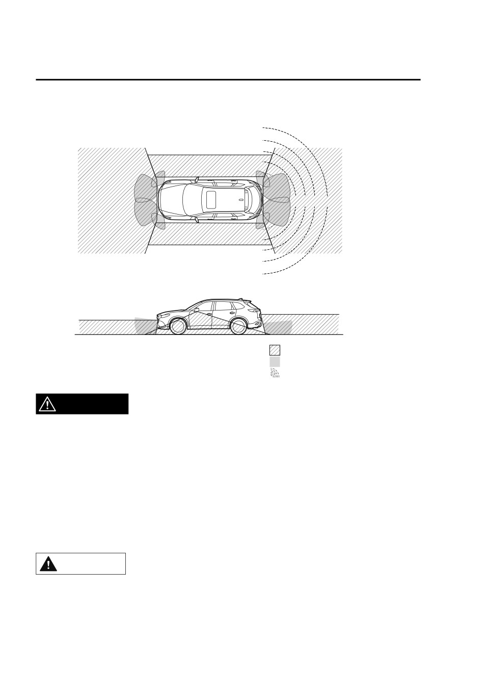
360°View Monitor Range
: Cameras
: Ultrasonic sensors
: Radar sensors (rear)
WARNING
Always confirm the safety of the area around the vehicle with the mirrors and directly with
your eyes when driving.
The 360°View Monitor is an auxiliary device which assists the driver in checking the safety of
the area around the vehicle.
The shooting range of the cameras and detection range of the sensors are limited. For
example, the areas in black at the front and rear of the vehicle image and the seams where
each of the camera images merge are blind spots where an obstruction may not be visible. In
addition, the extended vehicle width lines and projected vehicle path lines are only to be used
as references, and the images on the screen may differ from the actual conditions.
CAUTION
¾ Do not use the 360°View Monitor under any of the following conditions.
¾ Icy or snow-covered roads.
¾ Tire chains or a temporary spare tire is installed.
4-170
When Driving
i-ACTIVSENSE
¾ The front doors or the liftgate is not fully closed.
¾ The vehicle is on a road incline.
¾ The door mirrors are retracted.
¾ Do not hit the front/rear camera, front bumper, and door mirrors forcefully. The camera
position or installation angle may shift.
¾ The cameras are of a waterproof structure. Do not disassemble, modify, or remove a
camera.
¾ The camera cover is made of hard plastic, therefore do not apply oil film remover, organic
solvents, wax, or coating agents. If any such agent gets on the camera cover, wipe it off
using a soft cloth immediately.
¾ Do not rub the camera lens forcefully, or clean it with an abrasive or hard brush. Otherwise,
it could scratch the camera lens and negatively affect the images.
¾ Consult an Authorized Mazda Dealer for repair, painting, or replacement of the front/rear
camera, front bumper and door mirrors.
¾ Heed the following cautions to assure that the 360°View Monitor operates normally.
¾ Do not modify the vehicle suspensions or lower/raise the vehicle body, or both.
¾ Always use wheels of the specified type and size for the front and rear wheels. Consult an
Authorized Mazda Dealer for tire replacement.
¾ When the display is cold, images may leave trails or the screen might be darker than usual,
making it difficult to check the vehicle surroundings. Always confirm the safety at the front
and around the vehicle visually when driving.
¾ The method for parking/stopping the vehicle using the 360°View Monitor differs depending
on the road circumstances/conditions and the vehicle conditions. When and how much you
turn the steering wheel will differ depending on the situation, therefore always check the
vehicle surroundings directly with your eyes while using the system.
Also, before using the system, always make sure that the vehicle can be parked/stopped in
the parking/stopping space.
NOTE
If there are water droplets, snow, or mud on the camera lens, wipe it off using a soft cloth.
If the camera lens is especially dirty, wash it off with mild detergent.
If the area where the camera is installed, such as the liftgate or door mirrors, has been
damaged in a vehicle accident, the camera (position, installation angle) may have shifted.
Always consult an Authorized Mazda Dealer to have the vehicle inspected.
If the camera is subjected to excessive changes in temperature such as by pouring hot
water on the camera during cold weather, the 360°View Monitor may not operate
normally.
If the battery voltage is low, the screen might be temporarily difficult to view, however,
this does not indicate a problem.
4-171
When Driving
i-ACTIVSENSE
The 360°View Monitor has limitations. Objects under the bumper or near both ends of the
bumper cannot be displayed.
Obstructions above the upper image range of the camera are not displayed.
Under the following conditions, the screen might be difficult to view, however this does
not indicate a problem.
The temperature near the lens is high/low.
Rainy conditions, water droplets on the camera, or high humidity.
Mud or foreign matter near the camera.
Extremely bright light such as sunlight or headlights hitting the camera lens directly.
Because the 360°View Monitor camera uses a special lens, the distance displayed on the
screen differs from the actual distance.
Obstructions displayed on the screen may appear differently than in actuality.
(Obstructions may appear fallen, larger, or longer than they actually are.)
Do not apply stickers to a camera or the area around it. In addition, do not install
accessories or an illuminated number/character license plate to the area around a
camera. Otherwise, the camera may not correctly display the surrounding conditions.
4-172
When Driving
i-ACTIVSENSE
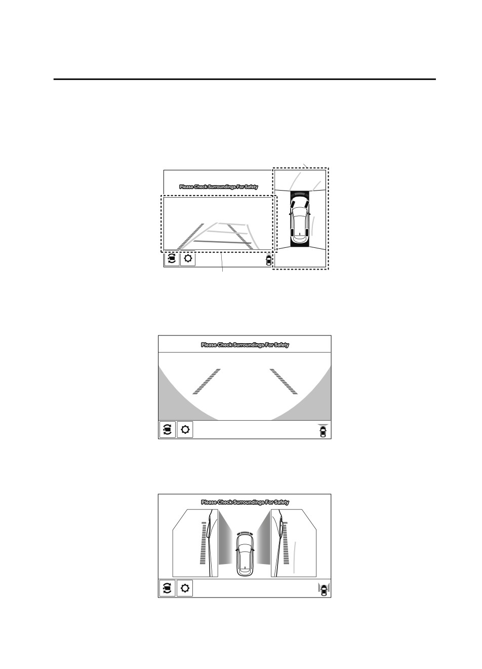
▼ Types of Images Displayed on the Screen
Top view/Front view
Displays the image of the area around the vehicle and the vehicle front.
Top view screen
Front view screen
Front wide view
Displays the image of the front of the vehicle (wide-area).
Side view
Displays the image of the left and right sides of the vehicle.
4-173
When Driving
i-ACTIVSENSE
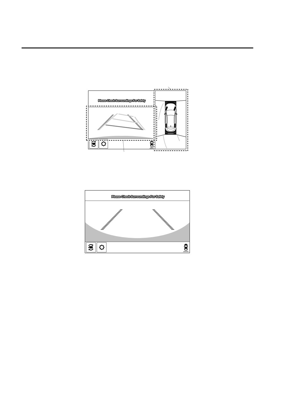
Top view/Rear view
Displays the image of the area around the vehicle and the rear of the vehicle.
Top view screen
Rear view screen
Rear wide view
Displays the image of the rear of the vehicle (wide-area).
4-174
When Driving
i-ACTIVSENSE
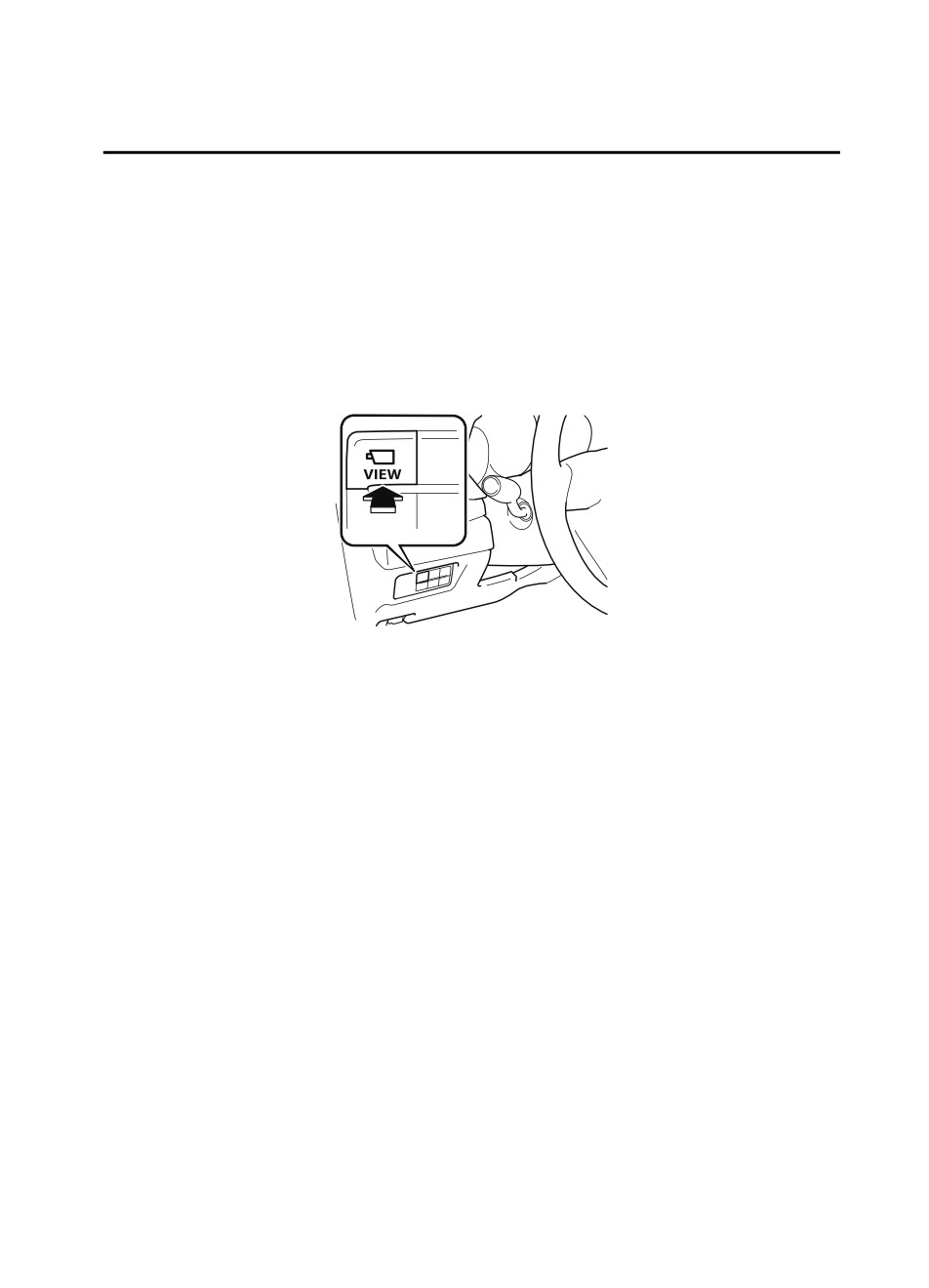
▼ How to Use the System
Top view/Front view, Front wide view, Side view
Indication
Images are displayed on the screen when the 360°View Monitor switch is pressed with all of
the following conditions met.
The ignition is switched ON.
The selector lever is in a position other than R.
4-175
When Driving
i-ACTIVSENSE
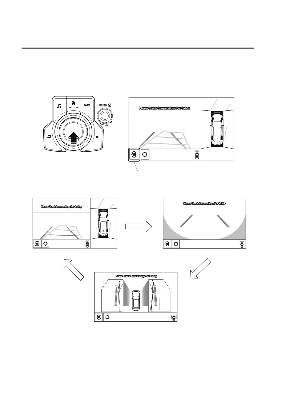
Display switching
You can change the displayed screen by pressing the commander knob or by touching the
switch camera icon on the screen while the top view/front view, front wide view, or the side
view is displayed.
Switch camera icon
Top view/Front view
Front wide view
Side view
NOTE
When the selector lever is in R position, the displayed screen does not switch to the top
view/front view, front wide view, or the side view.
Display of the top view/front view, front wide view, or the side view stops even with the
display conditions met if any of the following conditions occurs.
4-176
When Driving
i-ACTIVSENSE
When a switch around the commander knob is pressed.
The selector lever is shifted to P position (displayed when the selector lever is in a
position other than P).
(Displayed when vehicle speed is less than 15 km/h (9.3 mph))
4 minutes and 30 seconds have passed.
The vehicle speed is about 15 km/h (9.3 mph) or faster.
(Displayed when the vehicle speed is about 15 km/h (9.3 mph) or faster)
The vehicle speed is about 15 km/h (9.3 mph) or faster after 8 seconds have passed
since pressing the 360°View Monitor switch.
4 minutes and 22 seconds have passed from the point when the vehicle speed was less
than 15 km/h (9.3 mph) after 8 seconds have passed since pressing the 360° View
Monitor switch.
The 360°View Monitor displays the previously displayed screen.
The 360° View Monitor settings can be changed as follows.
Refer to the Settings section in the Mazda Connect Owner's Manual.
Automatic display of the 360°View Monitor when the ultrasonic sensor detects an
obstruction.
Automatic display of the 360°View Monitor when the ignition is switched ON.
Top view/Rear view, Rear wide view
The top view/rear view, rear wide view displays when all of the following conditions are
met.
The ignition is switched ON.
Selector lever is in R position.
4-177
When Driving
i-ACTIVSENSE
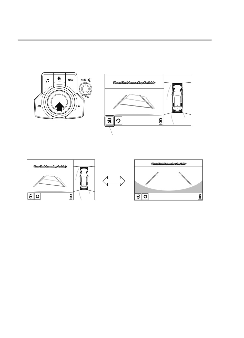
Display switching
The displayed screen can be switched by pressing the commander knob or by touching the
switch camera icon on the screen while the top view/rear view, rear wide view is displayed.
Switch camera icon
Top view/Rear view
Rear wide view
NOTE
The top view/rear view and rear wide view automatically display whether or not the 360°
View Monitor switch is turned on or off when shifting the selector lever to R position.
The setting can be changed to display the top view/front view when shifting from reverse
to a forward gear without operating the 360°View Monitor switch to check the front of the
vehicle while parallel parking.
Refer to the Settings section in the Mazda Connect Owner's Manual.
4-178
When Driving
i-ACTIVSENSE
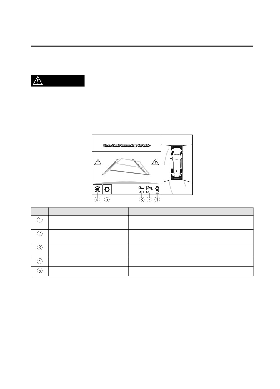
Screen operation/icon
WARNING
Always stop the vehicle when adjusting the 360°View Monitor image quality.
Do not adjust the 360°View Monitor image quality while driving. If you adjust the 360° View
Monitor image quality (such as brightness, contrast, tone, and color density) while driving, it
could lead to an unexpected accident.
(Display example)
Display/Icon
Content
View status icon
Indicates which image is displayed among the front view/front
wide view/side view/rear view/rear wide view.
Parking sensor status icon
Indicates that the parking sensor has a problem or it is switch-
ed off.
Rear Cross Traffic Alert (RCTA) status
Indicates that the radar sensor (rear) has a problem or it is
icon
turned off.
Switch camera icon
Each time the screen is touched, the display screen switches.
Setting icon
The image quality for the 360°View Monitor can be adjusted.
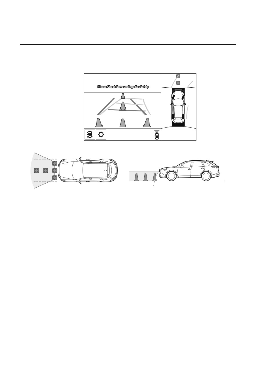
▼ Top View/Front View
Use the top view/front view to assist in checking the safety of the surrounding area when
accelerating from a stop, parking, or stopping the vehicle.
4-179
When Driving
i-ACTIVSENSE
Display range
(Screen display)
(Actual condition)
Target object
NOTE
In the top view screen, the areas in black at the front and rear of the vehicle image and the
seams where each of the camera images merge are blind spots.
Because images displayed in the top view screen are processed from each camera, the top
view screen may display in the following ways.
If an image containing an object with a conspicuous color is picked up by any of the
cameras, the whole screen may be affected and it may display in that color.
Obstructions displayed in the front view may not display on the top view screen.
If the position or angle of each camera changes due to tilting of the vehicle, the image
may appear distorted.
Lines on the road may appear distorted at the seams where each of the camera images
merge.
The entire screen may appear bright/dark depending on the illumination level around
any of the cameras.
4-180
When Driving
i-ACTIVSENSE
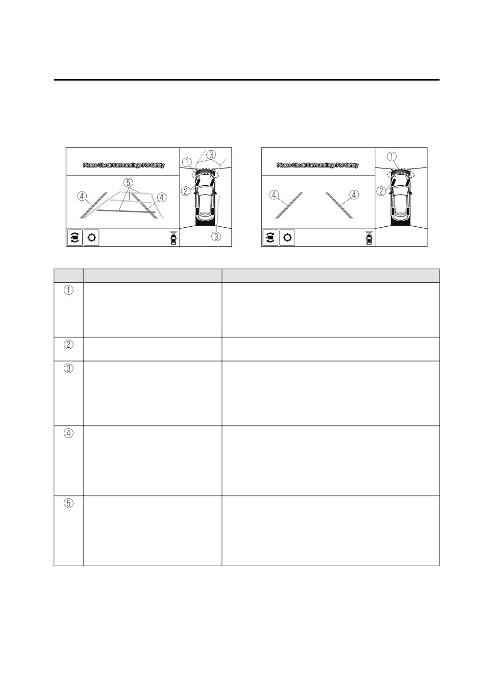
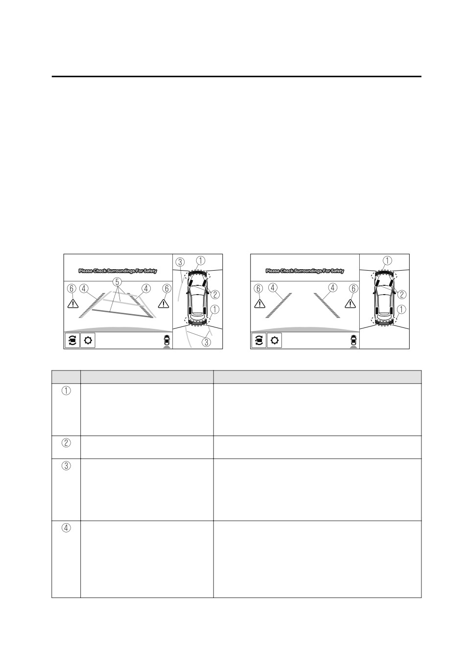
Viewing the screen
(When the projected vehicle
(When the projected vehicle
path line display is on)
path line display is off)
-a
-b
Display/Icon
Content
Parking sensor view
Displays the parking sensor detection condition when the
parking sensor is activated.
For details, refer to the parking sensor obstruction detection
indication and warning sound.
Refer to Parking Sensor System on page 4-260.
Tire icon
Indicates the tire direction. Moves in conjunction with the
steering wheel operation.
Projected vehicle path lines (yellow)
Indicates the approximate projected path of the vehicle.
Moves in conjunction with the steering wheel operation.
a) Indicates the path where the edge of the front bumper is ex-
pected to travel.
b) Indicates the path where the inner side of the vehicle is ex-
pected to travel.
Extended vehicle width lines and dis-
Indicates the approximate width of the vehicle and the dis-
tance guide lines (red/blue)
tance (from front end of bumper) in front of the vehicle.
The red lines indicate the points up to about 0.5 m (19 in)
from the front end of the bumper.
The blue lines indicate the points from about 0.5 m (19 in)
and up to 2 m (78 in) from the front end of the bumper.
Projected vehicle path distance guide
Indicates the distance (from front end of bumper) in front of
lines (red/yellow)
the vehicle.
The red line indicates the point about 0.5 m (19 in) from the
front end of the bumper.
The amber lines indicate the points about 1 m (39 in) and 2
m (78 in) from the front end of the bumper.
4-181
When Driving
i-ACTIVSENSE
CAUTION
The parking sensor detection range has limitations. For example, obstructions closing in from
the side and objects short in height may not be detected. Always confirm the safety around
the vehicle visually when driving.
For details, refer to the parking sensor obstruction detection indication and warning sound.
Refer to Parking Sensor System on page 4-260.
NOTE
The setting can be changed so that the projected vehicle path lines are not displayed.
Refer to the Settings section in the Mazda Connect Owner's Manual.
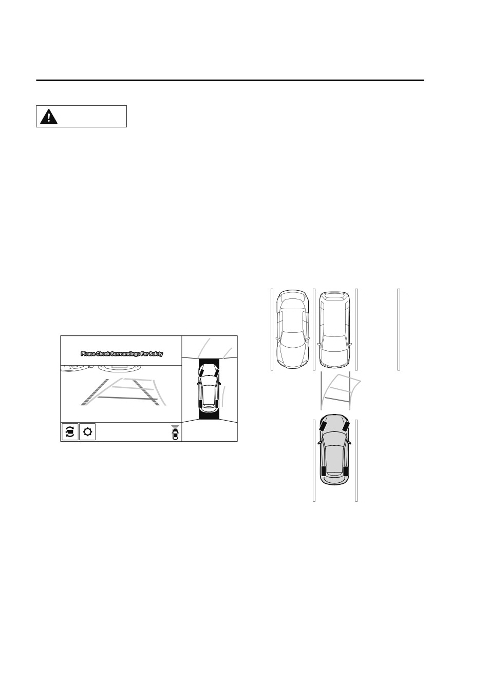
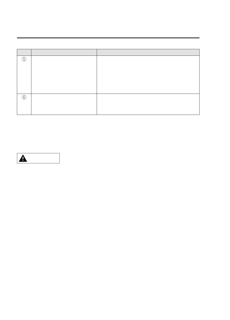
How to use the projected vehicle path line function
(Screen display)
(Actual condition)
Make sure that there are no obstructions within the projected vehicle path lines.
Drive the vehicle forward while turning the steering wheel so that no obstructions come
within the projected vehicle path lines.
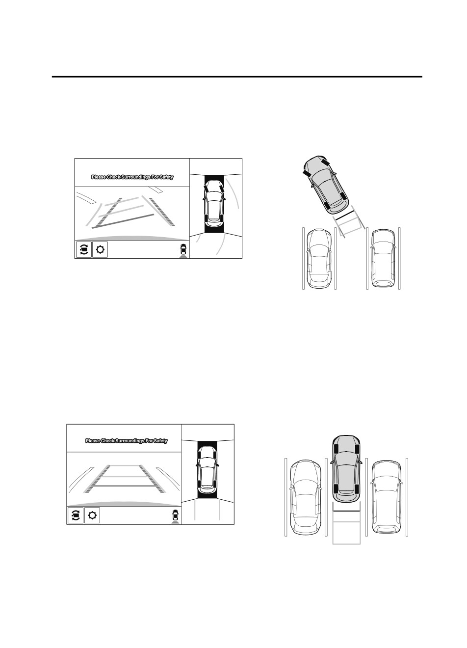
▼ Front Wide View
Use the front wide view to assist in checking the safety of the surrounding area when
accelerating from a stop or entering a T-shaped intersection and intersection.
4-182
When Driving
i-ACTIVSENSE
Display range
(Screen display)
(Actual condition)
Target object
Viewing the screen
Display/Icon
Content
Extended vehicle width lines and dis-
Indicates the approximate width of the vehicle and the distance
tance guide lines (red/blue)
(from front end of bumper) in front of the vehicle.
The red lines indicate the points up to about 0.5 m (19 in)
from the front end of the bumper.
The blue lines indicate the points from about 0.5 m (19 in)
and up to 2 m (78 in) from the front end of the bumper.
4-183
When Driving
i-ACTIVSENSE
NOTE
The parking sensor obstruction detection indication does not display. Switch the screen
display to the top view/front view or side view display if the parking sensor warning sound
is activated.
The front wide view screen displays the image in front of the vehicle at a wide angle and
corrects the image to help detect approaching obstructions from the side. Therefore, it
differs from the actual view.
▼ Side View
Use the side view to assist in checking the safety of the surrounding area when accelerating
from a stop, parking, or stopping the vehicle.
Display range
(Screen display)
(Actual condition)
Target object
Viewing the screen
(When the projected vehicle
(When the projected vehicle
path line display is on)
path line display is off)
Display/Icon
Content
Parking sensor view
Displays the parking sensor detection condition when the
parking sensor is activated.
For details, refer to the parking sensor obstruction detection
indication and warning sound.
Refer to Parking Sensor System on page 4-260.
4-184
When Driving
i-ACTIVSENSE
Display/Icon
Content
Projected vehicle path lines (yellow)
Indicates the approximate projected path of the vehicle.
Moves in conjunction with the steering wheel operation.
The projected vehicle path lines (yellow) indicate the path the
inner side of the vehicle is expected to travel.
Vehicle parallel guide lines (blue)
Indicates the approximate vehicle width including the door
mirrors.
Vehicle front end guide lines (blue)
Indicates the point about 0.25 m (9.8 in) from the front edge
of the vehicle (front edge of the bumper).
NOTE
The setting can be changed so that the projected vehicle path lines are not displayed.
Refer to the Settings section in the Mazda Connect Owner's Manual.
How to use the projected vehicle path line function
(Screen display)
(Actual condition)
A B
C
A B
C
Make sure that there are no obstructions within the projected vehicle path lines.
Turn the steering wheel so that the projected vehicle path lines travel inside of the
obstruction (A), and drive the vehicle forward until it passes the obstruction.
If the projected vehicle path lines are on an obstruction (B) or outside of the obstruction (C),
the vehicle may contact the obstruction when turning the vehicle sharply.
CAUTION
¾ The parking sensor detection range has limitations. For example, obstructions closing in
from the side and objects short in height may not be detected. Always confirm the safety
around the vehicle visually when driving.
For details, refer to the parking sensor obstruction detection indication and warning sound.
Refer to Parking Sensor System on page 4-260.
4-185
When Driving
i-ACTIVSENSE
¾ Do not turn the steering wheel any more until the vehicle has passed the obstruction, even
if the obstruction is not visible on the side view image. If the steering wheel is turned even
more, the vehicle may contact the obstruction if it is turned sharply.
NOTE
Because there might be a difference between the image displayed on the screen and the
actual conditions, always check the safety of the surrounding area using the mirrors and
directly with your eyes when driving.
Even though the object displayed on the screen, such as a road curb or a division line of a
parking space, and the vehicle parallel guide lines appear parallel, they may not actually
be parallel.
▼ Top View/Rear View
Use the top view/rear view to assist in checking the safety of the surrounding area when
accelerating from a stop, parking, or stopping the vehicle.
Range of displayed screen image
(Screen display)
(Actual condition)
Target object
NOTE
In the top view screen, the areas in black at the front and rear of the vehicle image and the
seams where each of the camera images merge are blind spots.
Because images displayed in the top view screen are processed from each camera, the top
view screen may display in the following ways.
4-186
When Driving
i-ACTIVSENSE
If an image containing an object with a conspicuous color is picked up by any of the
cameras, the whole screen may be affected and it may display in that color.
Obstructions displayed in the rear view may not display on the top view screen.
If the position or angle of each camera changes due to tilting of the vehicle, the image
may appear distorted.
Lines on the road may appear distorted at the seams where each of the camera images
merge.
The entire screen may appear bright/dark depending on the illumination level around
any of the cameras.
Viewing the screen
(When the projected vehicle
(When the projected vehicle
path line display is on)
path line display is off)
-b
-a
Display/Icon
Content
Parking sensor view
Displays the parking sensor detection condition when the
parking sensor is activated.
For details, refer to the parking sensor obstruction detection
indication and warning sound.
Refer to Parking Sensor System on page 4-260.
Tire icon
Indicates the tire direction. Moves in conjunction with the
steering wheel operation.
Projected vehicle path lines (yellow)
Indicates the approximate projected path of the vehicle.
Moves in conjunction with the steering wheel operation.
a) Indicates the path where the rear wheels are expected to
travel.
b) Indicates the path where the outer side of the vehicle is ex-
pected to travel.
Extended vehicle width lines and dis-
These guide lines indicate the approximate width of the vehi-
tance guide lines (red/blue)
cle and distance to a point measured from the rear of the vehi-
cle (from the end of the bumper).
The red lines indicate the points up to about 0.5 m (19 in)
from the rear end of the bumper.
The blue lines indicate the points from about 0.5 m (19 in)
and up to 2 m (78 in) from the rear end of the bumper.
4-187
When Driving
i-ACTIVSENSE
Display/Icon
Content
Projected vehicle path distance guide
These guide lines indicate the approximate distance to a point
lines (red/yellow)
measured from the rear of the vehicle (from the end of the
bumper).
The red line indicates the point about 0.5 m (19 in) from the
rear end of the bumper.
The amber lines indicate the points about 1 m (39 in) and 2
m (78 in) from the rear end of the bumper.
Blind Spot Monitoring (BSM) warning
Indicates when the Rear Cross Traffic Alert (RCTA) has oper-
lights
ated.
For details, refer to Rear Cross Traffic Alert (RCTA).
Refer to Rear Cross Traffic Alert (RCTA) on page 4-127.
NOTE
The setting can be changed so that the projected vehicle path lines are not displayed.
Refer to the Settings section in the Mazda Connect Owner's Manual.
How to use the projected vehicle path line function
CAUTION
¾ The front of the vehicle swings out wide when turning the steering wheel while reversing.
Maintain sufficient distance between the vehicle and an obstruction.
¾ The parking sensor detection range has limitations. For example, obstructions closing in
from the side and objects short in height may not be detected. Always confirm the safety
around the vehicle visually when driving.
For details, refer to the parking sensor obstruction detection indication and warning sound.
Refer to Parking Sensor System on page 4-260.
NOTE
Because there might be a difference between the image displayed on the screen, such as
indicated in the following, and the actual conditions when parking, always check the
safety at the rear of the vehicle and the surrounding area directly with your eyes.
Even though the back end of the parking space (or garage) displayed on the screen and
distance guide lines appear parallel, they may not actually be parallel.
When parking in a space with a division line on only one side of the parking space, even
though the division line and the vehicle width guide line appear parallel, they may not
actually be parallel.
The following shows an example of vehicle parking with the steering wheel turned to the
left while backing up the vehicle. When backing into a parking space from the opposite
direction, the steering operation is reversed.
4-188
When Driving
i-ACTIVSENSE
1. Back the vehicle into the parking space by turning the steering wheel so that the vehicle
enters the center of the parking space.
(Screen display)
(Actual condition)
2. After the vehicle starts entering the parking space, stop and adjust the steering wheel so
that the distance between the vehicle width lines and the sides of the parking space on
the left and right are roughly equal, and then continue backing up slowly.
3. Once the vehicle width lines and the sides of the parking space on the left and right are
parallel, straighten the wheels and back the vehicle slowly into the parking space.
Continue checking the vehicle's surroundings and then stop the vehicle in the best
possible position. (If the parking space has division lines, check whether the vehicle
width guide lines are parallel to them.)
(Screen display)
(Actual condition)
▼ Rear Wide View
Use the rear wide view to assist in checking the safety of the surrounding area when
accelerating from a stop, parking, or stopping the vehicle.
4-189
When Driving
i-ACTIVSENSE
Range of displayed screen image
(Screen display)
(Actual condition)
Target object
Viewing the screen
Display/Icon
Content
Extended vehicle width lines and dis-
These guide lines indicate the approximate width of the vehi-
tance guide lines (red/blue)
cle and distance to a point measured from the rear of the vehi-
cle (from the end of the bumper).
The red lines indicate the points up to about 0.5 m (19 in)
from the rear end of the bumper.
The blue lines indicate the points from about 0.5 m (19 in)
and up to 2 m (78 in) from the rear end of the bumper.
4-190
When Driving
i-ACTIVSENSE
Display/Icon
Content
Blind Spot Monitoring (BSM) warning
Indicates when the Rear Cross Traffic Alert (RCTA) has oper-
lights
ated.
For details, refer to Rear Cross Traffic Alert (RCTA).
Refer to Rear Cross Traffic Alert (RCTA) on page 4-127.
NOTE
The parking sensor obstruction detection indication does not display. Switch the screen
display to the top view/rear view display if the parking sensor warning sound is activated.
The rear wide view screen displays the image at the rear of the vehicle at a wide angle
and corrects the image to help detect approaching obstructions from the side. Therefore, it
differs from the actual view.
▼ Margin of Error Between Road Surface on Screen and Actual Road Surface
There might be some margin of error between the road surface appearing on the screen and
the actual road surface. A margin of error in the perceived distance could lead to an
accident, therefore be aware of the following conditions which can more easily produce
errors in the perceived distance.
The vehicle tilts due to weight of passengers and cargo.
If the vehicle is tilted, obstructions picked up by a camera can appear farther or closer than
the actual distance from the vehicle.
Front camera
Obstruction
Margin of error
4-191
When Driving
i-ACTIVSENSE
Side camera
Obstruction
Margin of error
Rear camera
Margin of error
Obstruction
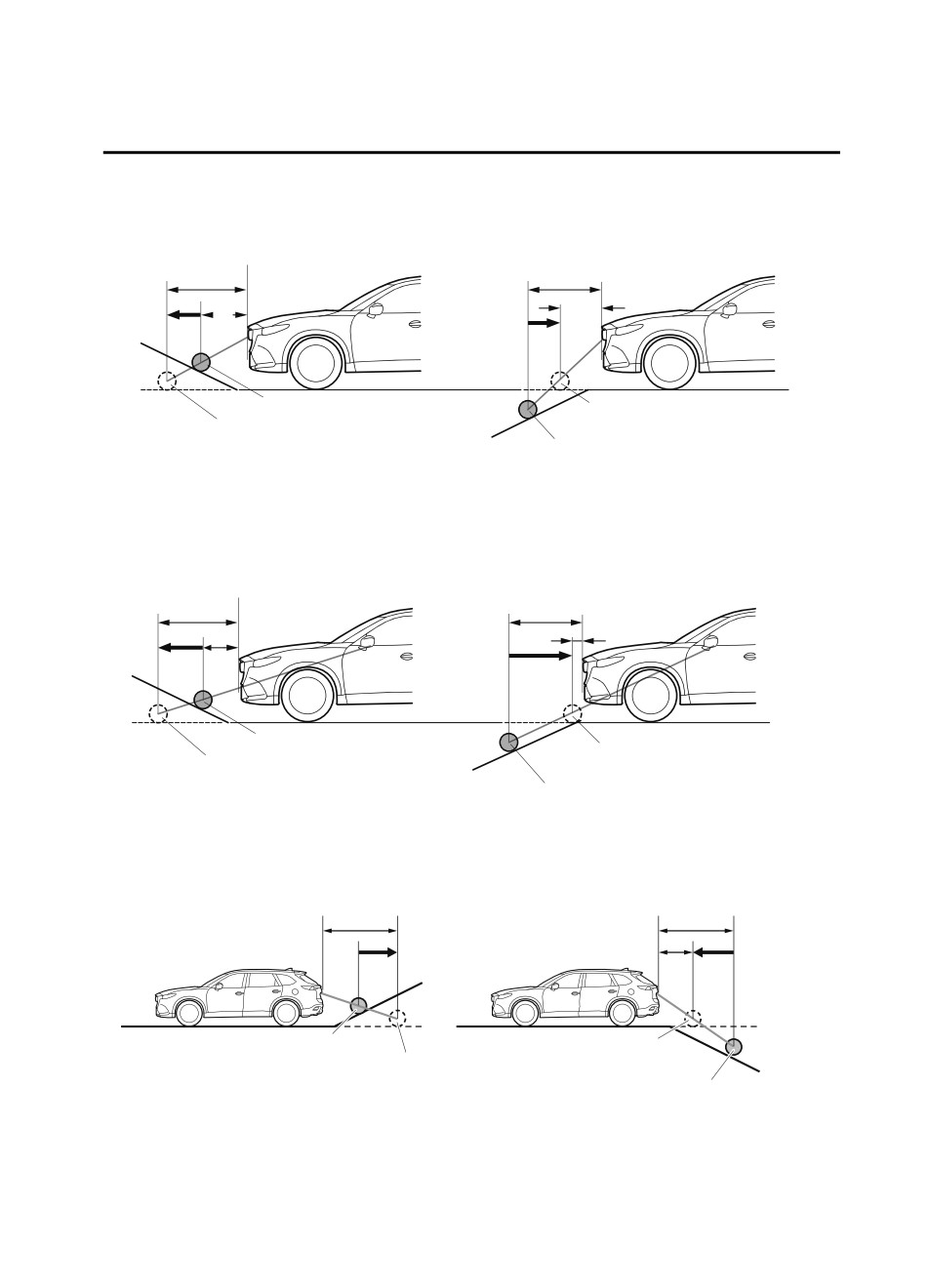
There is a steep up or down grade in the road at the front or rear of the vehicle
If there is a steep up or down grade in the road at the front or rear of the vehicle,
obstructions picked up by the camera can appear farther or closer than the actual distance
from the vehicle.
4-192
When Driving
i-ACTIVSENSE
Front camera
Appears further than
Appears closer than
actual distance
actual distance
A
B
B
A
Actual obstruction
Obstruction appearing
Obstruction appearing
on screen
on screen
Actual obstruction
A: Distance of obstruction being viewed on screen
B: Actual distance of obstruction from vehicle
Side camera
Appears further than
Appears closer than
actual distance
actual distance
A
B
B
A
Actual obstruction
Obstruction appearing
Obstruction appearing
on screen
on screen
Actual obstruction
A: Distance of obstruction being viewed on screen
B: Actual distance of obstruction from vehicle
Rear camera
Appears
Appears
A
farther than
B
closer than
B
actual
A
actual
distance
distance
Object at actual position
Object on screen
Object on screen
A: Distance between the vehicle and object displayed on the screen.
Object at actual
B: Actual distance between the vehicle and object.
position
4-193
When Driving
i-ACTIVSENSE
NOTE
If the vehicle is on a slope, obstructions taken by the camera can appear farther or closer
than the actual distance from the vehicle.
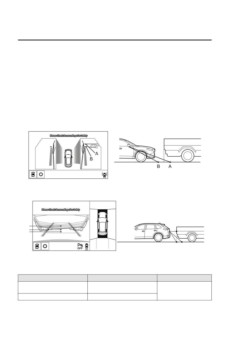
Three-dimensional object at vehicle front or rear
Because the vehicle front end guide lines (side camera) or the distance guide lines (rear
camera) are displayed based on a flat surface, the distance to the three-dimensional object
displayed on the screen is different from the actual distance.
Side camera
(Screen display)
(Actual condition)
Rear camera
(Screen display)
(Actual condition)
A
B
A
C
C B
Sensed distance on screen A > B > C
Actual distance B > C = A
▼ System Problem Indication
Center display indication
Cause
Action to be taken
“No image signal reception” is dis-
Have your vehicle inspected
The control unit might be damaged.
played
by an Authorized Mazda
Screen is pitch-black and blank
The camera might be damaged.
Dealer.
4-194
When Driving
i-ACTIVSENSE
360° View Monitor (Mazda Connect (Type B))*
▼ 360° View Monitor
The 360°View Monitor consists of the following functions which assist the driver in
checking the area surrounding the vehicle using various indications in the center display and
a warning sound while the vehicle is being driven at low speeds or while parking.
Top view
The top view displays an image of the vehicle from directly above on the center display
by combining the images taken from the 4 cameras set on all sides of the vehicle. The top
view displays on the right side of the screen when the front view or rear view screen is
being displayed. The top view assists the driver in checking the area surrounding the
vehicle when the vehicle is moving forward or in reverse.
Front view/front wide view
The image from the front of the vehicle is displayed on the center display.
The view from the front assists the driver in checking the front of the vehicle by
displaying guide lines on the displayed image taken from the front of the vehicle.
Side view
The images taken from the front left and right sides of the vehicle are displayed on the
center display.
The side view assists the driver in checking the front sides of the vehicle by displaying
guide lines on the displayed image taken from the front left and right sides of the vehicle.
Rear view/rear wide view
The image from the rear of the vehicle is displayed on the center display.
The image from the rear assists the driver in checking the rear of the vehicle by displaying
guide lines on the displayed image taken from the rear of the vehicle.
Parking sensor
If there are any obstructions near the vehicle while the top view/side view is displayed, an
obstruction detection indication turns on around the bumper in the center display.
The parking sensors use ultrasonic sensors to detect obstructions around the vehicle when
the vehicle is driven at low speeds, such as during garage or parallel parking, and notifies
the driver of the approximate distance from the vehicle to the surrounding obstruction
using sound and an obstruction detection indication.
Refer to Parking Sensor System on page 4-270.
Rear Cross Traffic Alert (RCTA)
If there is the possibility of a collision with an approaching vehicle while the rear view/
rear wide view is displayed, a warning is displayed on the center display.
The Rear Cross Traffic Alert (RCTA) uses rear side radar sensor to detect vehicles
approaching from the rear left and right sides of the vehicle, and it assists the driver in
checking the rear of the vehicle while reversing by flashing the Blind Spot Monitoring
(BSM) warning lights and activating the warning sound.
*Some models.
4-195
Большое спасибо!
Ваше мнение очень важно для нас.
Нет комментариевНе стесняйтесь поделиться с нами вашим ценным мнением.
Текст