Great Wall Florid. Manual — part 22
GWFLORID Maintenance Manual
86
Rear Suspension
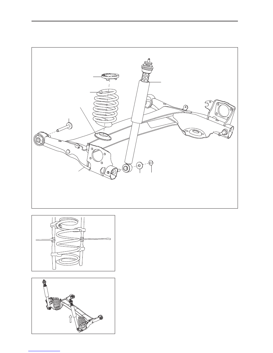
Components
Rear shock absorber and
rear coil spring removal
1. Hoist the vehicle with a jack, then remove the left and
right rear wheels.
2. During the removal of the rear twist beam, use SST (Special
Service Tools) to clamp the coil spring, so that it does not
pop out and cause injury.
3. Compression spring.
Hold up the rear twist beam upwards with a lift, compressing
the rear coil spring and damper.
Upper mounting rubber cushion
for the rear coil spring
Rear coil spring
Lower mounting rubber cushion
for the rear coil spring
Large washer
Rear twist beam assembly
Rear shock absorber subassembly
Hexagon bolt for flange face
Hexagon nut for flange face
F

87
Suspension System
Inspection, installation, and removal of the
trailing arm spindle sleeve assembly
1. Trailing arm spindle sleeve inspection.
(a) Inspect the trailing arm spindle sleeve for deformities,
shifting, partial or serious cracks, or loosening.
(b) If any existing damage of the trailing arm spindle
sleeve is not clearly seen, take the following steps:
Wash the trailing arm spindle sleeve's rubber areas with
clean water. Rub it clean with cotton meanwhile (shown
on the left). Check and make sure the rubber surface has
none of the previously mentioned flaws. If it does, re-
place with a new trailing arm spindle sleeve assembly.
2. Trailing arm spindle sleeve removal.
(a) Use a white paint pen to mark, and remember the trail-
ing arm spindle sleeve assembly direction.
(b) The trailing arm spindle sleeve is disposable. If
damaged, first use a pry bar to lift up the edge of the
trailing arm spindle sleeve's outer tube in order to
install the SST (Special Service Tools).
Rear twist beam assembly removal
1. Hold up the rear twist beam assembly with a lift, and
remove the rear shock absorber and rear coil spring.
For detailed steps, refer to the rear shock absorber and
coil spring removal.
2. Remove the hexagon bolt for flange face
Q151B12110TF2 + Q402 (d2=35 t=5) FD, and slowly
set down the twist beam (as shown on the left).
Tightening torque: 77
-
87 N·m
When removing bolts, check and ensure that the rear
twist beam is reliably supported, to avoid injury from it
falling.
4. Remove the rear shock absorber.
Screw down the hexagon nut for flange face Q32012T13F2
(M12×1.25) FD linking the rear shock absorber and rear
twist beam, and remove the rear shock absorber. Make sure
the rear twist beam is firmly supported meanwhile.
Tightening torque: 44
-
54 N·m
5. Remove the coil spring.
Slowly release the firmly supported rear twist beam, at
the same time support the coil spring, until the coil spring
loosens, then take it down.
Rear shock absorber
Large washer
Hexagon nut for
flange face
GWFLORID Maintenance Manual
88
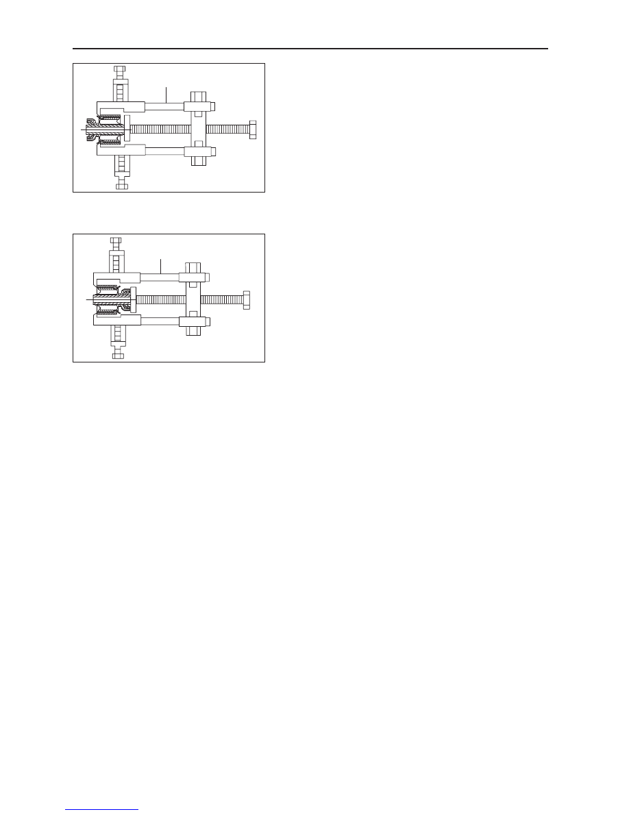
(c) Use SST (Special Service Tools) to clog the shaft
sleeve's installation tube. Tighten the two adjusting
bolts, use a wrench to twist the middle long bolt, and
push out the shaft sleeve.
SST
3. Install the new trailing arm spindle sleeve assembly.
(a) Before installing the new trailing arm spindle sleeve
assembly, first to distinguish the installation direction
for the trailing arm spindle sleeve's nylon bushing as-
sembly.
(b) Use SST (Special Service Tools) to clog the shaft
sleeve's installation tube. Tighten the two adjusting
bolts, twist the middle long bolt with a wrench, and
push in the shaft sleeve.
SST

89
Suspension System
Wheel and Tire
Tire
Remark
This vehicle's tire is of the tubeless type. The optimal design condition is met when the inflation pressure is at
the recommended value, and the tire is under full load. Maintaining suitable tire pressure and proper driving
habits greatly influence the tire's use life. For the vehicle, it improves riding comfort, stability, and handling. For
the tire, it reduces tread wear, damage to the tire and extends tire life. Overloading, speeding, and unnecessary
emergency braking will all add to the tire's wear and tear.
Tire pressure measurements should be taken under normal temperature. If the tire pressure rises due to motion
generated heat when driving, cooling it will return to the normal temperature. Therefore, do not deflate the tire
when the air pressure has risen to this point. The tire's air pressure will naturally and slowly decrease when used
under normal conditions. Hence please inspect the air pressure regularly (suggested once a month). The spare
tire should be kept in a useable condition at all times.
Inspect the tire pressure when it is cool monthly or before a long drive. Adjust the tire pressure to the recom-
mended level. The air pressure will normally rise because the tire warms up due to movement. Therefore, after
driving, you absolutely must not deflate or reduce the tire's air pressure, as deflating could reduce the cool tire's
air pressure.
Tire inflation
During a new tire's initial stage of use, warning due to bending motions will cause the tire to swell, and thus
reduce the corresponding air pressure. After 24 hours or 2000-3000 km worth of drive, charge the air pressure.
After inflating, check if the air nozzle core is leaking air with soapy water, then lock on the cap.
Possible problems caused by tire pressure
Exceeding the recommended air
pressure
Below the recommended air pressure
Same vehicle axle, different
air pressure
Possible problems it
can create
1. Bumpy ride
2. The tear or rupturing of the tire
3. Rapid wear of the tire tread's center
1. Noisy turns
2. Uneasy turns
3. Tread edge wear is accelerated and uneven
4. The tire's rim is damaged or ruptured
5. The tire cord ruptures
6. High tire temperature
7. Steering failure
8. Large oil consumption
1. Uneven braking
2. Over steering
3. Steering failure
4. Deviation while accelerating
Tire and wheel (steel wheel) installation instructions
When installing the tire and wheel, the tire's radial hardware components, also called "high spot", should be at
the same level of the wheel's minimum radius or so called "low spot".
The "high spot" of the tire is initially marked by the paint spot on the side of the tire's surface. This paint will
eventually be washed away.
The "low spot" of the wheel is initially marked by a paint spot on the wheel flange. Whenever the tire is
removed from the wheel, the tire and wheel need re-balancing to make sure the vehicle runs smoothly. If no
paint spot is found on the tire, draw a line on the tire and the wheel before they are removed, in order to make
sure that the tire and the wheel will be re-assembled at the same place.
Tire replacement
When a tire needs to be replaced, make sure to use a tire with the same specification as the original one. A new
tire used for replacement must be of the same dimension, load area, and structure as the original one. Using tires
that are different in dimension or type will influence the vehicle's riding comfort, handling, speedometer and
odometer calibration, vehicle ground clearance, and the clearance between the tire or the tire's snow chain and
the vehicle body or chassis.
It is suggested to use a new pair of tires on the same axle. If only one tire is needed to be replaced, make sure to
use a tire with a tread most similar to the original, so as to keep brake power and traction balanced.
Warning: Do not mix radial tires, bias tires, bias belted tires, etc., which are of different structure on the
same vehicle unless it is an emergency. Mixing different tires would seriously influence the vehicle's
handling and stability, and even possibly lead to losing control of the vehicle.
Нет комментариевНе стесняйтесь поделиться с нами вашим ценным мнением.
Текст