Great Wall Florid. Manual — part 47
GWFLORID Maintenance Manual
186
Immobilizer System
Immobilizer system composition
This vehicle's engine immobilizer system consists of a theft deterrent ECU assembly, a theft deterrent coil as-
sembly, and two theft deterrent converter assemblies. The theft deterrent coil assembly is put on the head of
ignition lock cylinder, with the other end connected to the theft deterrent ECU assembly. The two theft deterrent
converter assemblies are separately installed inside the plastic handles of the two keys.
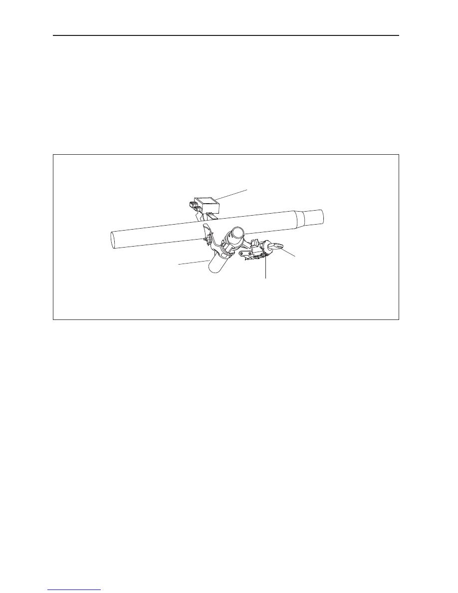
1. Position diagram
All the components of immobilizer system are assembled on the overall vehicle except for the theft deterrent
converter assemblies inside the keys. They achieve communication functions via the wire harness connections.
The following figure shows the position of each component in the overall vehicle.
Theft deterrent controller
Ignition lock key
Theft deterrent coil
Steering column
2. Theft deterrent controller
The theft deterrent controller assembly mainly consists of a microprocessor and peripheral components. It com-
municates with the password transmitter assembly and engine ECU. The theft deterrent controller assembly
communicates with the engine ECU via the W wire, while communicating with the theft deterrent transponder
assembly via radio frequency. The theft deterrent controller connects with the scanner via the K wire. Through
the scanner, it can initiate matching, state controlling, and malfunction diagnostic on the immobilizer system.
3. Theft deterrent coil
The theft deterrent coil assembly is installed on the ignition lock cylinder, the other end of wire harness
plug is connected to the theft deterrent controller assembly. The theft deterrent coil assembly can generate
an electromagnetic field to achieve communication between the theft deterrent controller assembly and the
password transmitter assembly.
4. Transponder
The theft deterrent transponder is installed inside the key handle. It has no power supply, maintains a small size,
and long use life. It acquires electric energy and transmission signals using the stimulation of the electromagnetic
field generated by the theft deterrent coil, so as to communicate with the theft deterrent controller assembly.

187
Electrical Accessories
Diagnostic
scanner
Engine ECU
Battery
+
-
Ignition switch
LED
620 Ω
LED
ON
ANTA
GND
ANTB
Battery
Ground
W wire
R wire
K wire
A4
A3
A1
A2
A8
A5
A7
B3
B2
B1
Coil
6. Theft deterrent controller's connecting plug
The theft deterrent controller has two connecting plugs: an 8-core A plug and a 3-core B plug.
Pin
Pin definition
B1
Coil terminal A
B2
Coil terminal B
B3
GND
Theft deterrent controller
8-core A plug
Coil 3-core B plug pin definition
7. Immobilizer system matching
System matching is defined as a composition of independent immobilizer system components: The theft deter-
rent controller assembly, theft deterrent transponder, theft deterrent coil assembly, and engine ECU are com-
bined into a immobilizer control system through relevant downline matching equipment or scanners.The engine
can only start up when the well matched immobilizer system works normally.
Engine immobilizer system fault diagnostic and troubleshooting
Immobilizer system failure will lead to the engine ECU being blocked and the engine unable to start up. It does
Pin
Pin definition
Rated working
voltage
Working
current
A1 Connected battery
positive pole
12 V
<200 mA
A2 Ground
0 V
<200 mA
A3 Connected LED
12 V
<50 mA
A4 Connected ON end
12 V
<50 mA
A5 Connected R wire
12 V
<200 mA
A6 No connection
A7 Connected K wire
12 V
<200 mA
A8 Connected W wire
12 V
<200 mA
Note: Do not connect the A3 pin if the vehicle does not
have a theft deterrent indicator lamp
5. Immobilizer system wire connection diagram

GWFLORID Maintenance Manual
188
not necessarily mean that engine start failure is due to a immobilizer system malfunction. The reasons for start-
ing engine failures are numerous, including factors like fuel, gas, fire, electricity, wires, etc. If the engine cannot
start, first check if the immobilizer system is working normally. This can be judged by looking at the flashing
theft deterrent indicator lamp which is located on the dashboard in front of the driver seat: Insert the key into the
lock cylinder and turn it to the "ON" position. If a legal key is used to start the engine, once the warning lamp is
connected to the ON end and the transponder is confirmed, the LED will remain unlit. Then when the ON end is
disconnected and the key is pulled out, the LED will shine for 0.25 s and darken for 4 s, as to act as a warning.
If an illegal key is used to start up the engine or there is something wrong with the system, the alarm indicator
lamp will shine for 0.25 s and darken for 4 s. If all is normal, then check the other parts of the engine. If abnor-
mal, first perform immobilizer system troubleshooting. A scanner can be used to judge if the immobilizer system
is working normally, but the precondition is that the scanner must be able to establish communication with the
theft deterrent controller.
1. If communication cannot be established, consider the following:
(a) Check whether the battery voltage is higher than 9 V
(b) Check whether the scanner plug is well contacted to the vehicle socket
(c) Use a multimeter to check whether the 7 pin of the OBD-II plug (diagnostic plug) is connected to the theft
deterrent controller's A7 pin
(d) Check whether the power supply of the theft deterrent controller is normal. (Use a multimeter to measure
whether the voltage of the theft deterrent controller's socket A1 pin and A2 pin is higher than 9 V)
(e) Then adopt the substitution method, which is to replace the theft deterrent controller to check if there is
anything wrong with the theft deterrent controller.
• If the failure is related to the theft deterrent controller, change it and initiate re-matching.
• If the failure has nothing to do with the theft deterrent controller, remove the electronic controller which
is connected to the alarm's K wire, such as the ABS controller, engine electrojet controller, airbag ECU
assembly, etc., as to ascertain if the present fault is caused by the wire harness connected with the theft
deterrent controller's K wire.
2. If communication can be established
Connect the scanner to the vehicle diagnostic port. Insert the key into the steering lock, and turn it to the "ON"
position, then select the scanner to check the immobilizer system's trouble code.
3. Security system troubleshooting
Investigate the problem and perform troubleshooting according to the trouble code on the scanner:
Trouble
code
Code
significance
Failure cause
Troubleshooting methods
B1000
Theft deterrent
controller
internal
malfunction
Theft deterrent coil open
circuit or short circuit. Theft
deterrent controller internal
malfunction.
Check whether the theft deterrent coil's connecting plug and
1.
the theft deterrent controller is well connected.
Check whether the theft deterrent coil's wire harness plug is sliding
2.
or touching each other.
Remove the theft deterrent coil plug, and then use a
3.
multimeter to check the resistance between the B1 and B2
pins. The normal resistance is about 5-30 Ω. If the resistance
is close to zero, that means the coil has been short circuited.
If the resistance is infinite, then it means the coil's circuit is
open. Measure the resistance between pins B1 and B3, and
B2 and B3, normally they are infinite. If the resistance gains
a certain value, then it means the coil is short circuited or
leaking electricity.
If there is nothing wrong with the coil, the next step is to
4.
check the theft deterrent controller. Adopt the substitution
approach, replace it with a non-matched new theft deterrent
controller or an theft deterrent controller which has been
reset (please refer to the immobilizer system component
replacement). Insert the key into the ignition lock and turn it
to the "ON" position and read the trouble code. If there is no
9000 failure, it means the replaced controller has an internal
malfunction, and the new replaced controller must be re-
matched.

189
Electrical Accessories
Trouble
code
Code
significance
Failure cause
Troubleshooting methods
B3040
W wire failure,
communication
There is no response from
the electrojet controller after
the theft deterrent controller
sends out communication
requests.
First check whether the two failures B043 and B0422
1.
coexist. If so, first solve these two problems.
Check whether the 8-core plug of the theft deterrent
2.
controller is well connected. Check whether the wire harness
connecting the A8 pin (N wire) of the 8-core plug and
electrojet is well connected, not short circuited, and has no
poor contact. Check whether the electrojet wire harness and
the connector is well connected.
Replace the alarm (please refer to the immobilizer system
3.
component replacement). Check whether the above failures
exist. If they do not, the fault most likely exists in the alarm.
Replace the electrojet (please refer to immobilizer system
4.
component replacement). Check whether the above failures
exist. If they do not, the fault most likely exists in the
electrojet.
B3042
W wire
grounding
Short circuiting happens
between the W wire and the
ground
Check whether the theft deterrent controller's 8-core plug
1.
wire harness is touching each other.
Check whether the wire harness which connects the 8-core
2.
plug's A8 pin (W wire) and the electrojet is short circuited to
the ground.
Replace the alarm (please refer to immobilizer system
3.
component replacement). Check whether the above failures
exist. If they do not, the fault most likely exists in the alarm
Replace the electrojet (please refer to immobilizer system
4.
component replacement). Check whether the above failures
exist. If they do not, the fault most likely exists in the
electrojet.
B3043
W wire and
power is short
circuited
Short circuiting happens
between the W wire (A8
pin) and the battery positive.
Check whether the theft deterrent controller's 8-core plug
1.
wire harness is touching each other.
Check whether the wire harness which connects the 8-core
2.
plug's A8 pin (W wire) and the electrojet battery positive has
short circuited
Replace the alarm (please refer to immobilizer system
3.
component replacement). Check whether the above failures
exist. If they do not, the fault most likely exists in the alarm
Replace the electrojet (please refer to immobilizer system
4.
component replacement). Check whether the above failures
exist. If they do not, the fault most likely exists in the
electrojet.
B3045
(vehicles
without
the theft
deterrent
indicator
lamp will
show this
trouble
code, but
it will
not affect
immobilizer
system
validation.)
LED has a
short circuit or
open circuit,
LED operates
abnormally
The wire harness (A3
pin) connected to the theft
deterrent indicator (LED)
has short circuited to the
ground. The wire harness
(A3 pin) connected to
the immobilizer indicator
(LED) has an open circuit.
Check whether the theft deterrent controller's 8-core plug
1.
wire harness is touching each other.
Check whether the wire harness which connects the 8-core
2.
plug's A3 pin and the immobilizer indicator has short
circuited to the ground.
Check whether the wire harness which connects the 8-core
3.
plug's A3 pin and the immobilizer indicator has an open
circuit.
Нет комментариевНе стесняйтесь поделиться с нами вашим ценным мнением.
Текст