Great Wall Hover. Manual — part 68
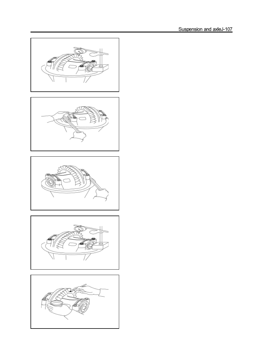
b. Adhere the measuring meter base on the end surface of reducer
housing; the measuring head contacts the tooth surface; rotate
the driven gear by hand and measure the engagement clearance be
tween the drive and driven gear.
c. If the engagement clearance does not meet the requirement, use
the special tools to adjust the left and right adjusting ring until it
meets the requirement.
d. Recheck the engagement clearance between the drive and driven
gear.
Engagement clearance: 0.13-0.18mm
14. Check the meshing mark of drive and driven bevel
gear.
a. Paint 3-4 teeth with the red lead in three different positions of
driven bevel gear.
b. Rotate the driven bevel gear in clockwise and anticlockwise by
hand.Check the engagement of gear.
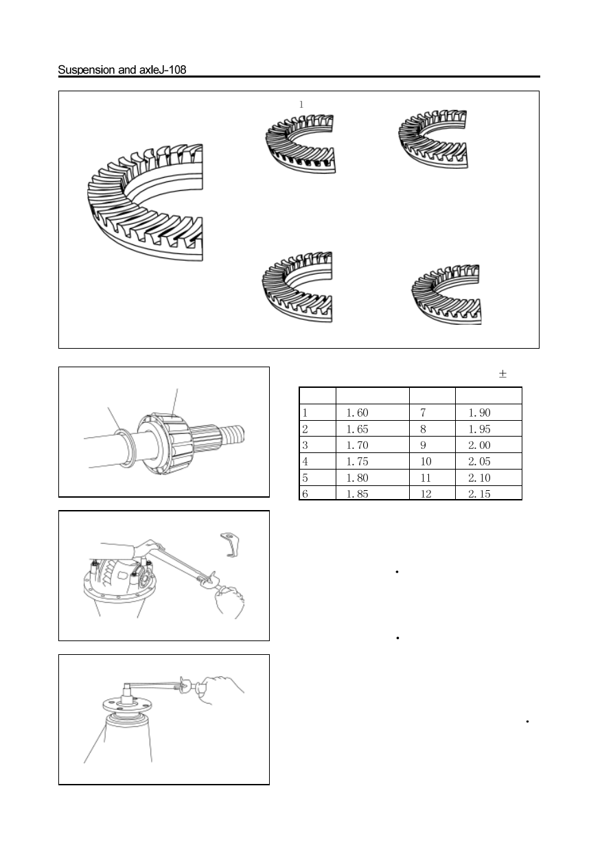
sound contact
toe contact
dedendum contact
arge end contact
small end contact
select the shim which can make the small drive gear
close to the driven bevel gear
select the shim which can make the small drive gear away from the driven bevel gear
Select the proper washer from the table for correction if the intertooth
contacting status is bad. The thickness tolerance of washer is
0.01mm.
15. Install the stop washer and stop plate
a. If the drive and driven gear engagement mark meets the requirement,
then use the hand hammer and punch to lock the stop washer.
b. Install the stop plate, spring shim and bolt; tighten the bolt.
Tightening force: 18-25N
m
c. Use the punch and hand hammer to knock the lower end of stop
plate in the adjusting ring hole.
Set NO. Thickness
Set NO. Thickness
16. Measure the total pre-applied load
Pre-applied load : 1.8-2.4N
m
If the pre-applied load is beyond the specified; it should replace the
shim between the spacer and rear bearing until meet the requirement.
a. It should replace the adjusting washer if the pre-applied load is
more than specified value.
b. If the pre-applied load is less than specified value, it can retighten
the nut slowly and the torque should be no more than 160N
m.
Caution: When tighten the nut, if is beyond the Max. torque, re-
place the adjusting washer and repeat the pre-applied load process.
Do not reduce the pre-applied load by the method of screw off the
drive gear nut to loose.
washer
rear bearing
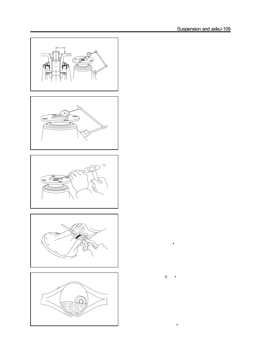
17. Check and adjust the run-out of flange.
a.Adhere the dial indicator base on the reducer housing; make the
probe of dial indicator contact with the end surface of flange;
rotate the flange and watch the rotation range of the dial.
Full run-out tolerance of end surface: 0.10mm
b.Adhere the dial indicator base on the reducer housing; make the
probe of the dial indicator contact with the inner diameter of
flange; rotate the flange by hand , and watch the rotation range of
the dial.Radial full run-out tolerance: 0.10mm
18. Rivet the nut of drive bevel gear
Installation of reducer and differential assembly
1.Install the new stiffening ring
2.Install the reducer and differential assembly
Install the reducer and differential assembly in the rear axle housing;
place the washer and nut. Tighten the nut to the specified torque.
Tightening force: 18-25N
m
3.Install the reducer and differential assembly flange
on the drive shaft flange and align the assembly
mark; use four bolts and nuts to connect them.
Tighten the bolt and nut to the specified torque.
Tightening force: 78
5N
m
4.Install the oil drain plug; fill the differential with the
gear oil
oil number : GL-5 hyperbolic gear oil
Viscosity: SAE80W/90
Amount: Filled with oil until the oil flow out from the oil filling
port.
Tighten the oil filling plug.
Tightening force: 140-150N
m
assembly mark
Differential
Differential
1
Remove the reducer and differential assembly
(Refer to “Removal of reducer”)
2
Remove the differential from the reducer and dif
ferential assembly.
(Refer to “Disassembly of reducer”)
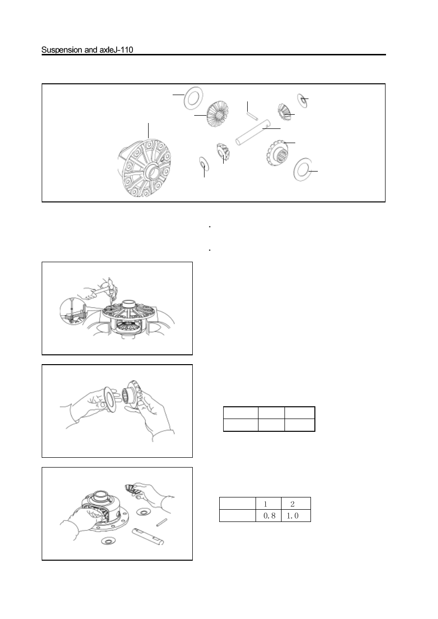
Replacement of differential components
1.Disassembly of differential
Use the hammer and punch to knock out the pin. Remove the
planetary gear shaft, two half axle gears, two planetary gears and
two lock washers, two thrust plates.
2. Assembly of differential
a.Install the half axle gear and thrust plate of axle shaft gear
(Unit: mm)
b.Install the planetary gear and planetary gear lock washer in the
differential by rolling. (Unit: mm)
differential housing
thrust plate
half axle
gear
straight pin
planetary gear
lock washer
half axle
gear
thrust plate
planetary gear
lock washer
planetary gear shaft
Set NO. 1 2
Thickness 1.2 1.5
Set NO.
Thickness
Нет комментариевНе стесняйтесь поделиться с нами вашим ценным мнением.
Текст