Great Wall Hover. Manual — part 64
23. Use the bolt coated with screw lock agent toconnect
the clump weight bracket welded assembly to the front
reducer housing and tighten it to the specified torque.
Specified torque : 20-26N
m
24.Use the bolt coated with screw lock agent to
connect the clump weight assembly to the clump
weight bracket assembly and tighten it to the speci-
fied torque.
Specified torque : 20-26N
m
The amount of screw lock agent could cover the screw.
25.Use the pneumaticto screw two studs on the correspon
ding screw hole on the front axle housing until the
limitation.
26. Coat the plane of front axle housing with the
continuous 1596 silicon rubber plane sealant, scrape
it to level by plate.
Caution: Avoid the screw hole when paint the sealant; prevent
the sealant enters into the screw hole.
27. Install the front reducer assembly on the front
drive axle housing and screw on the hexagon bolt and
spring washer combination; cap the spring washer on
the stud, tighten the nut to the specified torque.
(The screw of all bolts should be precoated with screw lock agent)
The specified tightening force of hexagon bolt and spring washer
combination, stud and nut should be: 18-25N
m
Caution: The bolt should be tightened in diagonal sequence
evenly; check the reducer housing and axle housing contacting
surface for gap; check the sealant from break. It should
remove the reducer for reinstallation if has the gap or break.
28. Screw the oil filling plug with washer on the front
drive axle.
Caution: Do not tighten it.
29. Screw the oil drain plug on the front drive axle.
Specified torque : 30-35N
m
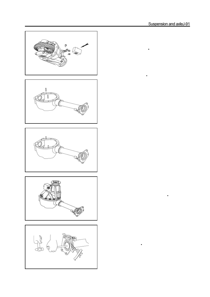
30. Use the special tools to install the major semiaxle
oil seal in the front axle tube.
Caution: Precoat the lip of oil seal with thin lithium base grease
and the oil seal should be installed in position.
(It should coat the screw of the stud which is screwed
in the front axle housing with the screw lock agent, and
the amount should be just can cover the screw which is
screw in the front axle housing)
Caution: The position of stud should consist with that before
disassembly.
31.Use the special tools to install the needle bearing in
the major semiaxle.
32.Use the special tools to install the major semiaxle
bearing by press..
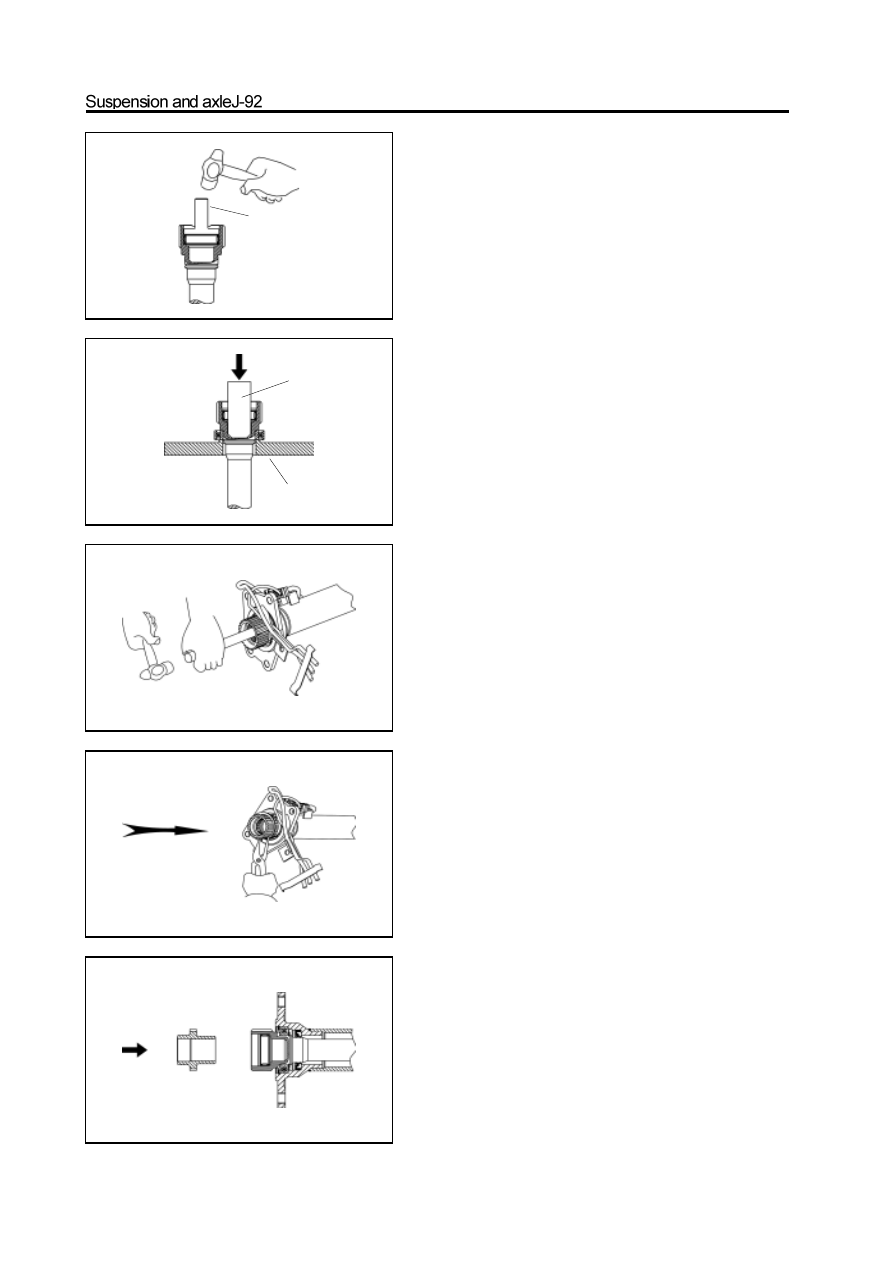
33. Use the circlip pliers to install the circlip to clamp
the bearing inner race of major semiaxle.
34.Insert the spline on small end of major semiaxle
into the spline of front reducer half axle gear; use
the brass rod and hand hammer to knock the major
semiaxle into the front reducer.
Caution: Does not damage the inside needle bearing.
On spline of large end of major semiaxle when
knock in the major semiaxle.
35.Use the circlip pliers to install the circlip in the
flange and clamp the major semiaxle bearing outer
race.
36. Push the mechanical wheel of separator into
theneedle bearing inner race in major semiaxle until
can not move.
special tools
special tools
special tools
electric clutch detector
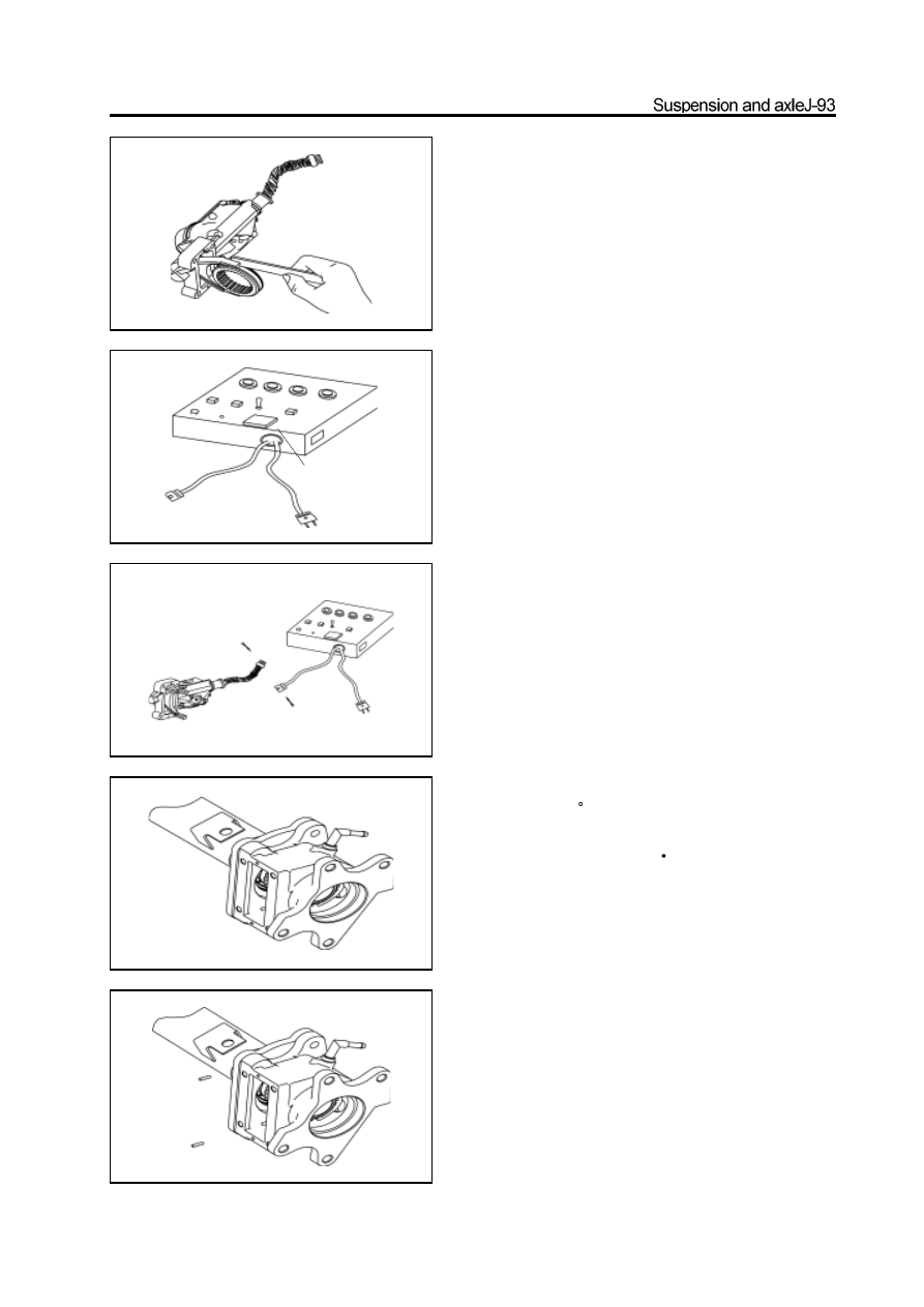
37. Detect the electric clutch assembly .
a. Measure the clearance between the shift fork and shift fork
sleeve.
Range of clearance : 0.2-0.4mm
It should replace the electric clutch assembly and shift fork
sleeve when the clearance is not in the range.
b. Connect the electric clutch assembly to the electric clutch
detector and power the electric clutch detector with 220V
power supply to test the electric clutch (Before the test,
adjustthe test controller status to make the motor starting time
is 3s ,the time form found the actuator is not in position to
restartingis 2.5s and the time of controller to redrive the
electric clutch is2s) The motor starts for 3s when the gear
switch is shifted form 2WD to 4WD, the lamp flashes at the
same time, the clutch is in 4WD status, the indicator lamp is
light always. If does not reach the 4WD status in the first
time, then the controller restarts it for 2s after 2.5s delay, the
lamp flashes at the same time; if it is still not in position, then
the indicator lamp flashes twice continuously, the indicator
lamp is extinguished for 1s, the motor is stopped. That means
the electric clutch is unqualified and should be replaced by the
qualified product. The motor starts for 3s normally when the
clutch is shifted form 4WD to 2WD, the lamp flashes at the
same time, when the clutch is in 2WD status, the indicator
lamp is extinguished always. If does not reach the 2WD status
in the first time, then the controller restarts it for 2s after 2.5s
delay, the lamp flashes at the same time; if it is still not in
2WD status, then the indicator lamp flashes twice
continuously, the indicator lamp is extinguished for 1s, the
motor is stopped.
That means the electric clutch is unqualified and should be
replaced by the qualified product.
38. Cover the shift fork sleeve on the major
semiaxle spline.
39. Install the separator housing on the front axle
tube flange and use the bolt to tighten it to the
specified torque
(The bolt should be precoated
with the screw lock agent and the amount should be
just can cover the complete screw)
specified torque : 90-110N
m
Caution: Before installation, remove the foreign material on
two matching surfaces of separator housing and front axle
tube flange; and precoat the 1596 silicon rubber plane sealant
on the front axle tube flange. Caution: Prevent the sealant
from entering into the screw hole.
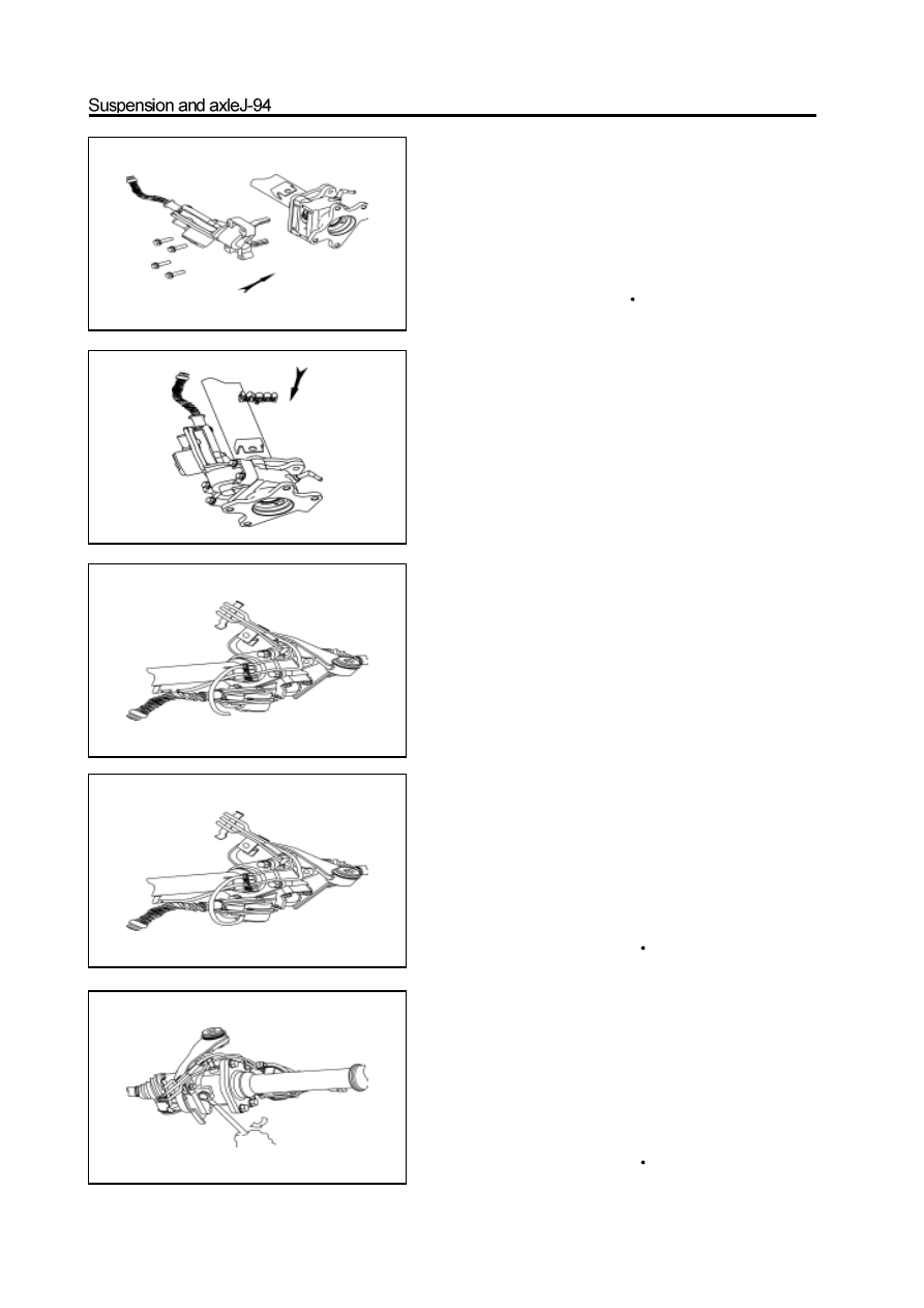
40. Press in the plastic vent tube on the electric
clutch housing and front axle tube.
41. Install two location pins in the location pin hole
of electric clutch housing respectively.
42. Coat the connecting surface of electric clutch
housing and electric clutch with 1596 silicon rubber
sealant uniformly; level it by plate.
Caution: The connecting surface should be cleaned
and must not have the oil and other foreign
matters. The sealant must not enter into the elec-
tric clutch housing and screw hole.
44.Insert the clip into the vent tube bracket.
45. Clamp the vent tube clip on the front drive axle
vent tube connecting tube assembly.
46. Connect the front drive axle vent tube connecting
tube assembly to three ports, the front axle tube,
electric clutch and electric clutch housing.
43. Install the electric clutch assembly on the electric
clutch housing.
a. Make the shift fork cross on the shift fork sleeve.
b. Align the location pin hole of electric clutch with two
location pins, and tighten it by bolt; tighten the bolt to the
specified torque. (Precoat the medium screw of bolt with one
or two drop of screw lock agent)
Specified torque : 23-26N
m
47. Screw off the oil filling plug of front drive axle
housing, then fill the axle housing with the hypoid
gear oil; then tighten the oil filling plug to the speci-
fied torque.
Gear oil number: GL-5
Filling amount: The oil level is flush with the lower edge of oil filling
port.
specified torque : 140-150N
m
48. Fill the electric clutch housing with the gear oil ;
then tighten the oil filling plug to the specified
torque.
Gear oil number: GL-5
Filling amount: The oil level is flush with the lower edge of oil filling
port.
Specified torque: 140-150N
m
Нет комментариевНе стесняйтесь поделиться с нами вашим ценным мнением.
Текст