Great Wall Hover. Manual — part 99

Safety airbag-16
Yes Next
step
4
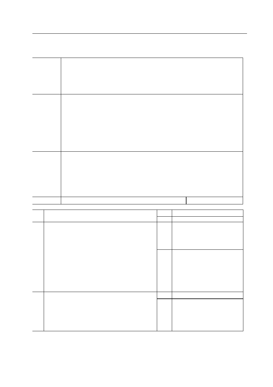
Confirm the failure in clock spring or other parts
configure the special tools fuel and temperature diagnostic instrument
at 2Ω position
Install back the accumulator negative wire
Place the ignition switch in ON place
Any failure code in display?
No
Replace clock spring
Take references in the removal
and installation for safety airbag
system and clock spring.
Normal
Replace SRS safety airbag
system unit; take references in
removal/installation of SRS
safety airbag system unit.
5
Check the wiring harness between clock spring and SRS safety airbag
system electronic-control unit
Place the ignition switch in LOCK position
Release accumulator negative wire and wait for 1 minute plus
Remove PAB trim cover, glove box (passengers’ side safety airbag is
under the trim cover)
Release the passengers’ side safety airbag module connector clip
Release all SRS safety airbag system unit connector clips
Check whether the following troubles are with the harness between
connector clips terminals of SRS safety airbag system unit and clock
spring
Grounding
Power-supply shorting
Shutoff
Is the previous wiring harness normal?
Abnormal
Replace the wire harness
Normal Next
step
6
Check the clock spring connector clip
Remove the steering pillar shell
Release the clock spring connector clip
Is the clock spring connector clip normal?
Abnormal
Replace the wiring harness or
connector clips
Normal Next
step
7
Check clock spring
Remove clock spring
Take references in removal/installation of safety airbag system as
well as clock spring
Check clock spring
Take references in the test for safety airbag system and clock spring.
Is the clock spring normal?
Abnormal
Replace clock spring
Take references in the
removal/installation of safety
airbag system and clock spring.
Normal Next
step
8
Check the wiring harness between clock spring and SRS safety airbag
system electronic-control unit
Place the ignition switch in LOCK position
Release accumulator negative wire and wait for 1 minute plus
Remove PAB trim cover, glove box (passengers’ side safety airbag is
under the trim cover)
Release the passengers’ side safety airbag module connector clip
Release all SRS safety airbag system unit connector clips.
Check whether the following troubles are with the harness between
connector clips terminals of SRS safety airbag system unit and spring
clock.
Grounding
Power-supply shorting
Shutoff
Is the previous harness normal?
Abnormal
Replace clock spring
Take references in the
removal/installation of safety
airbag system, and clock spring
Safety airbag-17
Passengers’ side failure
Failure code
$9015
$9016
$9018
$9019
Passengers’ side safety airbag module (high or low resistance or shorting grounding)
Test condition
Warning
If not correctly handled, the safety airbag module as well as pretension safety belt may possibly be
trigged, released and tensioned, thus make serene damage to people. Therefore, please carefully read the
repairing warning before trouble handling. Please take references in safety airbag system repairing warning
If with passengers’ side safety airbag failure
The resistance between SRS safety airbag system unit connector clip stitch 13 and stitch 14 not within the
designated scope.
The wiring harness shorting between safety airbag system unit stitch 13 and stitch 14
Open loop between SRS safety airbag system unit connector clip stitch 13 and stitch 14,
Possible causes
Passengers’ side safety airbag module failure
The failure of connector clip between passengers’ side safety airbag module and SRS safety airbag system
electronic-control unit
The failure of connector clip between SRS safety airbag system unit and grounding jumper.
The circuit shutoff or shorting between passengers’ side safety airbag module and SRS safety airbag system
electronic-control unit
The circuit shutoff or shorting between SRS safety airbag system unit and grounding jumper
SRS safety airbag system unit failure
Procedure Test
Operation
Yes Next
step
1
Is the vehicle with passengers’ side safety airbag module
No Step
5
Yes
Present failure code
Next step
History- accumulated failure codes
Next step
2
Check passengers’ side safety airbag connector clips
Warning
If not correctly handled, the safety airbag module may possibly be
trigged and released thus cause serene damage to people, therefore,
please carefully read the maintenance warning.
Take references in safety airbag maintenance warning.
Place the ignition switch in LOCK position
Release accumulator negative wire and wait for about 1 minute
plus
Remove the PAB trim cover, glove box (passengers’ side safety
airbag is under the trim cover)
Release passengers’ side safety airbag module connector clip
Is the previous connector clip normal?
No
Replace the wiring harness
Yes
Next step
3
Confirm whether the failure cause is with passengers’ side safety
airbag module or some other parts
Connect a better module to the terminal A and B of passengers’
side safety airbag connector clip
Connect the accumulator negative wire
Place the ignition switch in ON position
Any failure code in display?
No
Replace passengers’ side safety airbag
module
Take references in the
removal/installation of passengers’ side
safety airbag module in safety airbag
system.

Safety airbag-18
Normal
Present failure code
Replace SRS safety airbag system
unit
Take references in
removal/installation of SRS
safety airbag system unit in safety
airbag system.
History-accumulated failure
codes
The end of failure diagnosis
4
Check the wiring harness between passengers’ side safety airbag
module and SRS safety airbag system electronic-control unit
Place the ignition switch in LOCK position
Release accumulator negative wire and then wait for about 1
minute plus
Remove steering pillar shell
Release clock spring connector clip
Release driver’s and passengers’ side safety airbag module
connector clips
Release all SRS safety airbag system unit connector clips
Check whether the following troubles are with the circuit of the
connector clips terminals between SRS safety airbag system
electronic-control unit and passengers’ side safety airbag
module
Grounding
Power-supply shorting
Shutoff
Is the previous circuit normal?
Abnormal
Replace the relative wiring
harness
Impact-vehicle diagnosis
Test SRS-ECU diagnostic signals
1. Connect the (X-431 diagnostic test’s) diagnostic joint
2. Read the diagnostic results with X-431 diagnostic tester
Repairing procedure
1.When safety airbag is released.
The following parts should be replaced with new ones
a. Passengers’ side safety airbag module
b. SRS-ECU
c. Driver’s side safety airbag module
2 Check the following parts; replace them with new ones providing something wrong with them.
a. Clock spring
b. Steering-wheel, steering column, bottom steering shaft module
3.Driver’s side safety airbag module’s installation status towards the steering wheel.
a. Check whether abnormal knocking is with the steering wheel, its activity is in good condition and its clearance is normal.
b. Check whether the wiring harness joint is broken and its terminal is deformed.
Caution: Due to the impact, the diagnostic instrument cannot communicate with SRS-ECU when accumulator is lack of
power, in this case, check and maintain the instrument panel wiring harness or utilize the extension power supply.
Appendix-1
A important parts assurance and request. . . . . . . . . . .1
B non-metal materials consumption table. . . . . . . . . ...12
C Special tools. . . . . . . . . . . . . . . . . . . .14
D important working regions and tightening torque
important working region. . . . . . . . . . . . . . . 17
E Electric wiring diagram . . . . . . . . . . . . . . . ..18
Appendix
Нет комментариевНе стесняйтесь поделиться с нами вашим ценным мнением.
Текст