Great Wall Hover. Manual — part 23
Automatic transmission-23
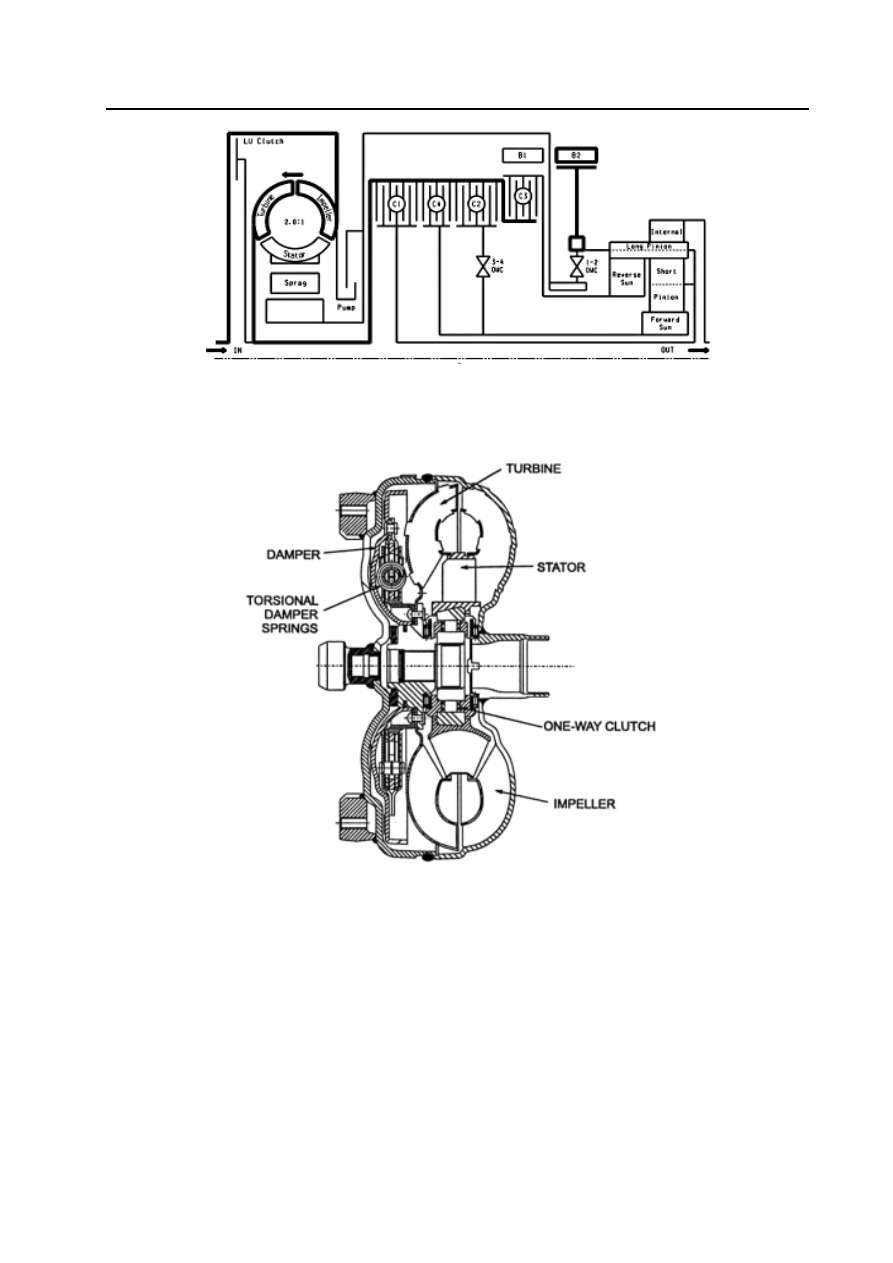
Figure 4.1 Power flow chart
Torque converter
The torque converter (refer to Figure 4.2) consists of the turbine, stator, impeller and a lock throttle brake and piston assembly.
Same as that of the traditional torque converter, the impeller is connected to the end cover of the torque converter. The turbine is
connected to the input shaft through the spline. The stator is installed on the pump housing through the one-way clutch .
Figure 4.2 Section of torque converter
The buffer and piston assembly can make the torque converter is locked in proper condition. The locking action only occurs
in the condition of specified throttle position opening and vehicle speed. When the hydraulic force makes the buffer and piston
assembly is coupled on the cover of torque converter, it can acquire the locking status. In this status, it can eliminate the
unnecessary sliding. It can increase the economical efficiency of fuel oil when the locking action is generated. When in locking
status, the torque buffer spring in the buffer and piston can absorb the torque fluctuation of engine
.
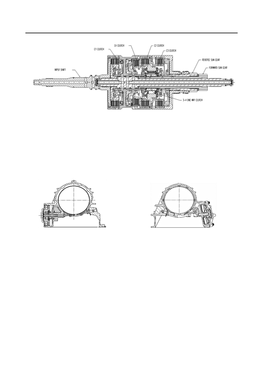
Clutch assembly
It has four types of clutch assembly (refer to Figure 4.3). All clutch assemblies are composed of several layers of steel plate and
friction disk.
Clutch C1 When it is engaged, the drive shaft drive the planet carrier. The condition occurs in 3
rd
and 4
th
Gear.
Clutch C2 When it is engaged, the drive shaft drive the forward central gear through the 3-4 one-way clutch. The conditio
occurs in 1
st
, 2nd and 3
rd-
Gear condition.
Clutch C3 When it is engaged, the drive shaft drive the backward central gear. The condition occurs in R-Gear position.
Clutch C4 It can provide the brake of engine during overspeed when is engaged, The condition occurs in manual 1
st
, 2
nd
and 3
rd
–Gear, also in automatic 2
nd
and 3
rd
-Gear to avoid the unfavorable inertia rotation of freewheel.
Automatic transmission-24
Front servo and brake belt
Rear servo and brake belt
Figure 4.4 brake belt
One-way clutch
The transmission has two one-way clutches, 1-2 one-way clutch and 3-4 one-way clutch (notice that the third one-way clutch is
located on torque converter, also called as retainer)
1-2 one-way clutch is located between the planet carrier assembly and central shaft. The structure makes the planet carrier only
can rotate in single direction around the central shaft. The one-way clutch is only engaged in automatic 1
st
-Gear.
3-4 one-way clutch is located between the clutch C4 and clutch C2.The structure makes the clutch C2 drive the front planetary
gear in 1
st
, 2
nd
and 3
rd
–Gear, but is disengaged in 4
th
-Gear and overspeed.
Planetary gear assembly
The planetary gear block used in transmission is the traditional lavena gear block consisted of6 pinions.
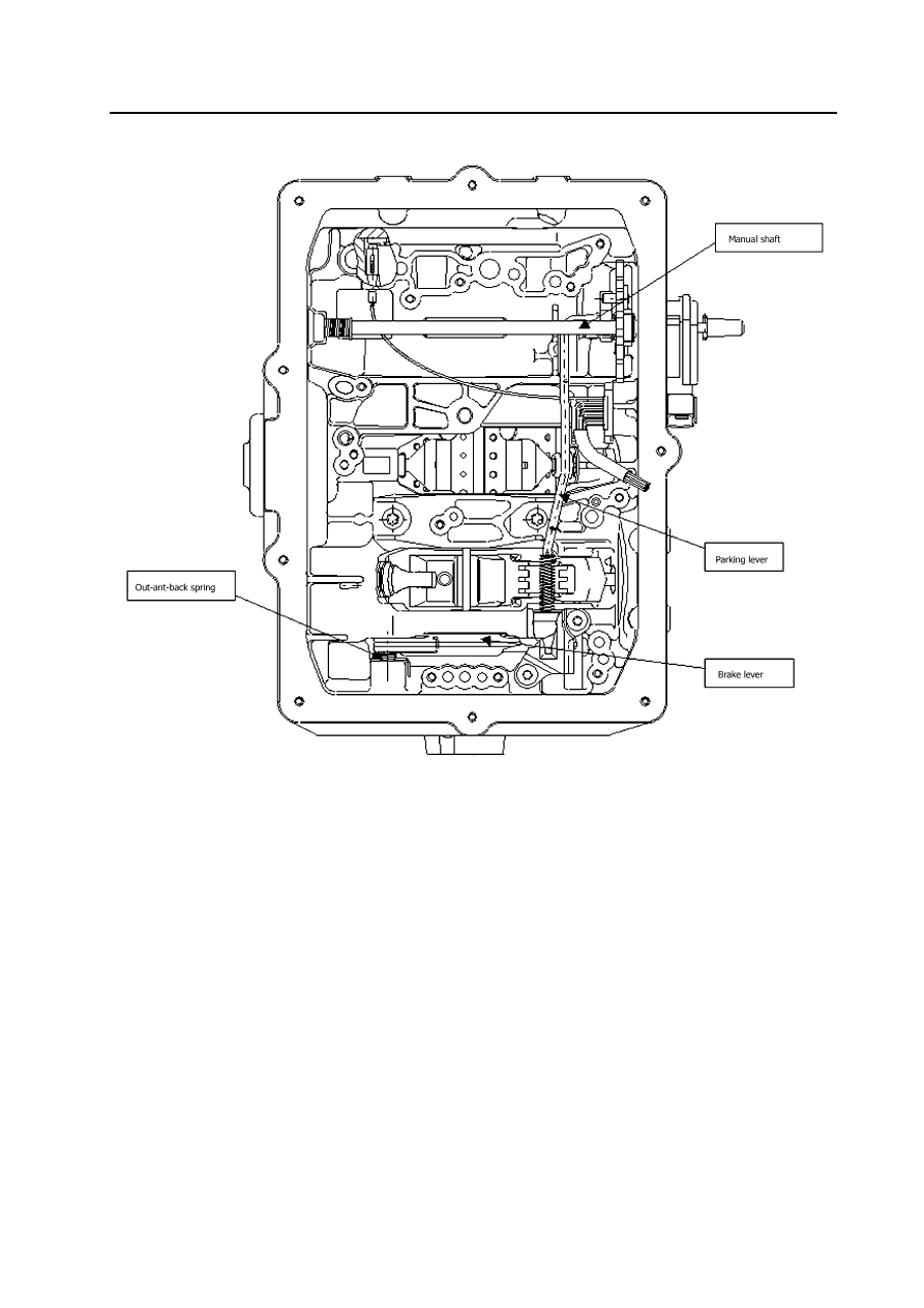
Parking mechanism
When select the parking-Gear, the steering column will move the parking lever backwardly to engage with the parking ratch
(refer to Figure 4.5). The ratchet is engaged with the tooth of external gear ring fear to lock the output shaft axle in the
transmission. When it is not in parking-gear, the return spring will release the parking ratchet and unlock the output shaft to
prevent the occurrence of accident parking action.
Figure 4.3 Clutch assembly
Brake belt
The transmission has two brake belts, brake belt B1 (named as 2-4 brake belt sometimes ) and brake belt B2 (named as low-speed
– reverse gear brake belt ) refer to Figure 4.4.
The brake belt B1 is a flexible brake belt which is engaged with front servo piston. When it is in 2
nd
and 4
th
–Gear, the brake belt
B1 starts to act. When the brake belt acts, it can prevent the rotation of reverse central gear by maintaining the clutch C3 assembly
is in static. In 2
nd
–Gear, only the external surface of piston is used. In 4
th
Gear, both sides are used to acquire more clamping force.
The brake belt B2 is a solid brake belt which is meshed with the rear servo piston. When the B2 acts, it prevents the rotation of
planet carrier assembly. When in manual 1
st
-Gear, only the external surface of piston is used. In reverse-Gear, both sides are used
to acquire more clamping force.
Automatic transmission-25
Figure 4.5 Parking mechanism
Automatic transmission-26
Power transmission
Introduction
It has the following power transmission pointed to different Gear-position:
power transmission
N-Gear and P-Gear
power transmission
R-Gear
power transmission
manual 1
power transmission
Automatic 1
st
-Gear
power transmission
Automatic 2
nd
-Gear
power transmission
Automatic 3
rd
-Gear
power transmission
Automatic 3
rd
-Gear locking
power transmission
Automatic 4
th
-Gear (overspeed -gear)
power transmission
Automatic 4
th
-Gear locking
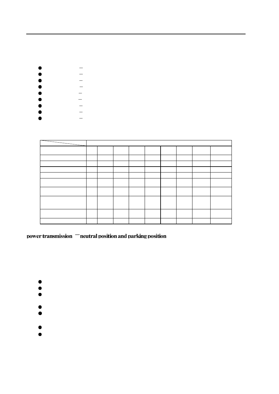
For description of each kind of power transmission condition, refer to following parts.
Table 5.1 describe the on-off condition of each unit in all gear condition.
Name
of
participated
unit
Position
C1
C2
C3 C4 B1 B2 1-2
OWC
3-4
OWC
LU
clutch
Parking and neutral position
-
-
-
-
-
X -
-
-
Reverse
-
-
X - X -
-
-
Manual 1
st
-Gear
-
X
-
X - X - X
Automatic 1
st
- Gear
-
X
-
-
-
-
X
-
Auto 2
nd
-Gear and manual
2
nd
-Gear
-
X
-
X X -
-
X
-
Automatic 3
rd
–Gear and
manual 3
rd
-Gear
X X
-
X -
-
-
X
-
Automatic 3
rd
-Gear locking
and manual 3
rd
-Gear
locking
X X
-
X -
-
-
X
X
Automatic 4
th
-Gear
(overspeed -gear)
X X
-
-
X -
-
-
-
Automatic 4
th
-Gear locking
X X
-
-
X -
-
-
X
In P-Gear or N-Gear, the planetary gear assembly has not the drive. The rear brake belt is used to eliminate the voice generated in
engagement with reverse gear and increase the application of 4WD. It is without the engagement of clutch and brake belt.
In parking-Gear, the locking of mechanism is realized through the engagement of brake lever installed on housing and tooth of
output shaft gear ring.
Control
In stabl
e status, to maintain the arrangement, the status of solenoid valve and valve is shown as follows:
solenoid valve S1 and S2 is powered off.
The line (pump) pressure is applied on the primary regulating valve (PRV) and electromagnetic supply valve.
The torque converter, oil cooler and lubrication loop are filled up with the transmission fluid from the primary regulating
valve.
The line pressure 500 loop is filled up with the transmission fluid from the electromagnetic supply valve.
S5 will be filled up with the transmission fluid through the variable pressure
\regulating valve (S5) .
The line pressure is prohibited form entering into the drive loop through the manual-operated valve .
B1 loop and all clutch loop are opened to drainage port.
Нет комментариевНе стесняйтесь поделиться с нами вашим ценным мнением.
Текст