Great Wall Hover. Manual — part 87
CD Player and Air Conditioning System-2
CD Player
Function Overview
This product is a kind of car audio system with VFD multi-information integrated display screen with such functions as PLL
electronic tuning radio, CD playing and operation & control of air conditioning system, it can receive AM, FM and FM stereo
radio broadcast programs, play CDs, electronically operate and control the air conditioning system of the car. The integrated
display screen can display the working state of the radio, CD player, air conditioning system, operating mode as well as
information concerning the equalizer, clock and the temperature inside and outside.
Wiring Instructions(see the diagram)
with the speakers: the amplifier of main unit of this system is designed with 4-channel BTL output, each speaker must
be wired individually; the phase position and place of the speaker must be connected correctly; please disconnect the
player from the power supply before connecting the speaker so as to avoid the short-circuit.
2. Connecting main unit with the integrated display screen:
Use the specially-supplied 12-pin connector cable to connect the VFD integrated display screen and main unit.
3. Connection of power supply, output and communication line of main unit:
At first, connect the communication cable of the 20-pin connector plug to the air conditioner ECU, then connect the speaker
output line to other lines, finally connect the yellow memory power supply cord (10A fuse tube) directly to the positive role of
accumulator; when all the wiring is completed, connect the red power supply cord (1A fuse tube) to the positive power supply
of the ignition lock.
4. Connecting main unit with the antenna
Typical antenna: insert the plug of coaxial cable of car’s antenna into the antenna socket of main unit.
Automatic antenna: insert the plug of coaxial cable of car’s antenna into the antenna socket of main unit, then connect the blue
antenna control cable in the 20-pin connector to the automatic antenna control end, connect the positive pole line of power
supply of automatic antenna to the positive pole of accumulator and the negative pole line to the earth.
5. Connecting main unit with CD-change box
CD player and the CD-change box are connected with the signal cables.
Prior to the installation, please be sure to remove three protective screws on the CD-change box and have it pasted with
ant-dust paper. If the protective screws are not removed, CD can not be played normally.
Attention: Improper wiring may result in the damage to the player!
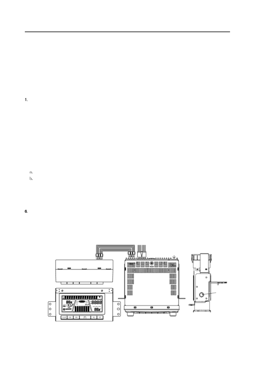
(Figure 7-1) Wiring Diagram
integrated display screen
12-pin connector cable
20-pin connector cable
antenna adaptor
main unit
CD Player and Air Conditioning System-3
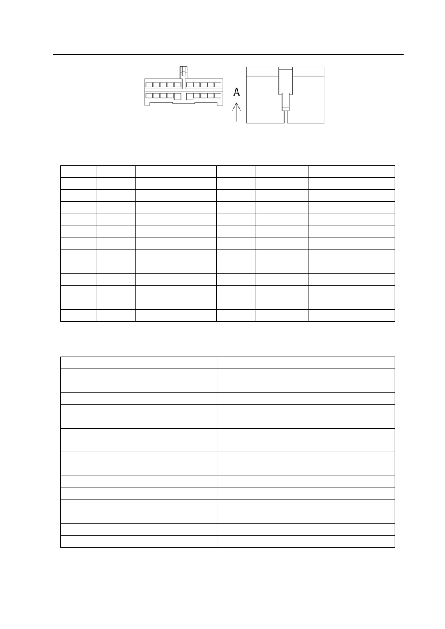
(Figure 7-2) cable position of 2-pin connector socket
Pos. No.
Color
Function
Pos. No.
Color
Function
1
White
Send the data (TX)
11
Shielded cable
Earthing of data cable
2
Red
Receive the data (RX)
12
—
—
3
Brown
Telephone mute (TEL)
13
Blue
Automatic antenna (ANT )
4
Orange
Lighting (LAMP)
14
Red
Ignition power supply (ACC)
5
—
— 15
Grounding
wire
6
—
—
16
Yellow
Memory power supply B+
7
White and
black
Front left speak (-FL-)
17
Green and black
Rear left speak (-RL-)
8
White
Front left speak (+FL+)
18
Green
Rear left speak (+RL+)
9
Gray and
black
Front right speak (-FR-)
19
Violet and black
Rear right speak (-RR-)
10
Gray
Front right speak (-FR+)
20
Violet
{
Rear right speak (+RR+)
Possible Troubles of CD Player, Inspection and Analysis
Trouble Descriptions
Possible causes, inspection and solutions
No programs received for AM and FM
Check if the antenna is pulled out and socket becomes
loosened.
Impurity of sound after radio auto-searching
Tune to the correct radio station with manual tuning method
No sound of one speaker
Check the speaker and the socket or adjust the balance(front,
back, left and right)
Refuse to work
Check the power supply, or disconnect and connect the power
supply and restart the player.
No power supply
Check if the plug-in fuse and output plug is loosened and if the
fuse is burned down.
Single channel when played
Check if the speaker is in open-circuit and examine its plug
Not read CD
Check the CD type and if it is placed in reverse or scratched.
Display screen displaying bad
Check the connecting wire of display screen or adjust the
brightness level higher
Air conditioner refuses to start
Inspect the ECU of air conditioner and air conditioning system
Button failure of air conditioner
Inspect the ECU of air conditioner and air conditioning system
A-side View
CD Player and Air Conditioning System-4
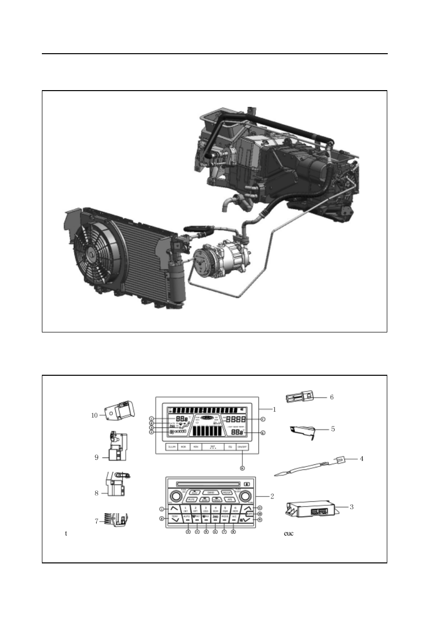
Air Conditioning System
Composition of Air Conditioning System
Air conditioning system mainly consists of air conditioner control unit, display unit, sensors and executor elements.
fresh air damper executor
mode damper executor
emperature damper executor
integrated display screen
CD Player
outside temperature sensor
inside temperature sensor
temperature sensor
of the evaporator
of the air conditioner
CD Player and Air Conditioning System-5
1. integrated display screen 2. CD player 3. Air conditioner ECU 4. Temperature sensor the evaporator 5. Outside
temperature sensor
6. Outside temperature sensor 7. Speed-adjusting module 8. Temperature damper executor 9. Mode damper executor
10. Fresh air damper executor
Definition of each button on CD player of air conditioner panel
[1] Button to increase the temperature [7] wind conveying mode button
[2] Button to decrease the temperature
[8] button to start air conditioner
[3] automatic operation button
[9] button to decrease the wind amount
[4] front-defrost button
[10] power-off button of air conditioner
[5] rear-defrost button
[11] button to increase the wind amount
[6] external circulation button
Definition of each button in air conditioning display zone of the integrated display screen
[1] display of inside temperature setting of air conditioner
[5] switch button of outside temperature display
[2] display of automatic operation of air conditioner
[6] display zone of outside temperature
[3] display zone of wind conveying mode of air conditioner
[7] clock display zone
[4] display zone of wind amount of air conditioner
Control and display unit:Control and display unit of the air conditioner mainly consists of:
Air conditioner ECU: The CC6460K model is designed with the individual air conditioner ECU to control the overall operation
of air conditioning system; Air conditioner ECU is installed under the bottom of CD player.The control panel of air conditioner
is designed with an integrated pattern with the control panel of CD player: to regulate, control and set the operation of the air
conditioning system.
Integrated display screen: display the working condition of air conditioning system of the car; relevant functions of air
conditioning system can be found to be displayed in different zone in the integrated display screen.
The sensor
Sensors of CC6460K Model automatic air conditioning system include: inside temperature sensor, outside temperature
sensor, temperature sensor executor of the evaporator.
Executor components include: mode selection executor motor, cold & hot executor motor, internal & external circulation
executor motor.
Trouble Diagnosis and Repair of Automatic Air Conditioning System
1. Self-diagnosis of the system
CC6460K air conditioning system is designed with the system self-diagnosis function. When the air conditioning system fails to
work, the self-diagnosis function designed for the car can be activated for the initial trouble diagnosis.
Operating directions:
At first, start the engine (turn the ignition switch from OFF to ON) and press OFF,
A U TO, RR and MODE successively and the
pressing of MODE switch shall last at least 2 seconds. The button must be pressed down within 10 seconds when the engine is
started (the ignition switch is turned to ON position).If the system is supposed to be released, then press A U TO switch or turn
off the ignition switch (OFF) .If one step is supposed to switch to another step, then press TEMP (HOT) or TEMP (COLD)
switch based on the needs.
Нет комментариевНе стесняйтесь поделиться с нами вашим ценным мнением.
Текст