Defender (1999-2002). Manual — part 67

26
COOLING SYSTEM
12
DESCRIPTION AND OPERATION
Viscous Fan Operation
A = Cold
B = Hot
1. Drive plate
2. Fan body
3. Clearance
4. Valve plate
5. Valve
6. Bi-metallic coil
7. Fluid seals
8. Ball race
9. Fluid chamber
10. Reservoir
11. Return port
When the engine is off and the fan is not rotating, the silicone fluid stabilises within the fluid chamber and the
reservoir. The fluid levels equalise due to the return port in the valve plate being open between the fluid chamber
and the reservoir. In this condition, when the engine is started, silicone fluid is present in the fluid chamber and
causes drag to occur between the drive plate and the body. This causes the fan to operate initially when the
engine is started.
As the fan speed increases, centrifugal force and a scoop formed on the fluid chamber side of the valve plate,
pushes the silicone fluid through the return port in the valve plate into the reservoir. As the fluid chamber empties,
the drag between the drive plate and the body is reduced, causing the drive plate to slip. This reduces the
rotational speed of the fan and allows it to ’freewheel’.
COOLING SYSTEM
13
DESCRIPTION AND OPERATION
When the coolant temperature is low, the heat emitted from the radiator does not affect the bi-metallic coil. The
valve remains closed, preventing fluid escaping from the reservoir into the fluid chamber. In this condition the fan
will ’freewheel’ at a slow speed.
As the coolant temperature increases, the heat emitted from the radiator causes the bi-metallic coil to tighten. This
movement of the coil moves the valve to which it is attached. The rotation of the valve exposes ports in the valve
plate which allow the silicone fluid to spill into the fluid chamber. As the fluid flows into the clearance between the
annular grooves in the drive plate and body, drag is created between the two components. The drag is due to the
viscosity and shear qualities of the silicone fluid and causes the drive plate to rotate the body and fan blades.
As the coolant temperature decreases, the bi-metallic coil expands, rotating the valve and closing off the ports in
the valve plate. When the valve is closed, centrifugal force pushes the silicone fluid through the return port,
emptying the fluid chamber. As the fluid chamber empties, the drag between the drive plate and the body is
reduced and the body slips on the drive plate, slowing the rotational speed of the fan.

COOLING SYSTEM
1
ADJUSTMENT
DRAIN AND REFILL
Service repair no - 26.10.01
WARNING: Hot coolant
Drain
1. Remove engine acoustic cover.
2. Visually check engine and cooling system for
signs of coolant leaks.
3. Examine hoses for signs of cracking, distortion
and security of connections.
4. Position drain tray to collect coolant.
5. Remove expansion tank filler cap.
6. Loosen clip screws securing air inlet hose to
intercooler and inlet manifold, release and
remove hose.
7. Release clip and disconnect bottom hose from
radiator.
8. Allow cooling system to drain.
9. Disconnect bottom hose from radiator.
Refill
1. Flush system with water under low pressure.
2. Do not use water under high pressure as it could
damage the radiator.
3. Connect bottom hose to radiator and secure
hose with clip.
4. Prepare coolant to required concentration.
5. Position heater temperature control to maximum
hot position.
6. Remove bleed screw from top hose.
7. Fill system slowly through coolant expansion
tank until a steady flow of coolant is emitted from
the bleed hole in top hose.
8. Fit bleed screw to top hose.
9. Continue filling system until coolant level
reaches ’MAX’ mark on expansion tank.
10. Fit expansion tank filler cap.
11. Position air intake hose and tighten clip screws.
12. Start and run engine until normal running
temperature is reached.
13. If fitted, DO NOT operate air conditioning.
14. Switch off engine and allow to cool.
15. Check for leaks and top-up coolant to ’MAX’
mark on expansion tank.
COOLING SYSTEM
1
REPAIR
COUPLING - COOLING FAN
Service repair no - 26.25.19
Remove
1. Remove battery cover.
2. Disconnect battery negative lead.
3. Remove 3 bolts and remove engine acoustic
cover.
4. Remove cooling fan cowl.
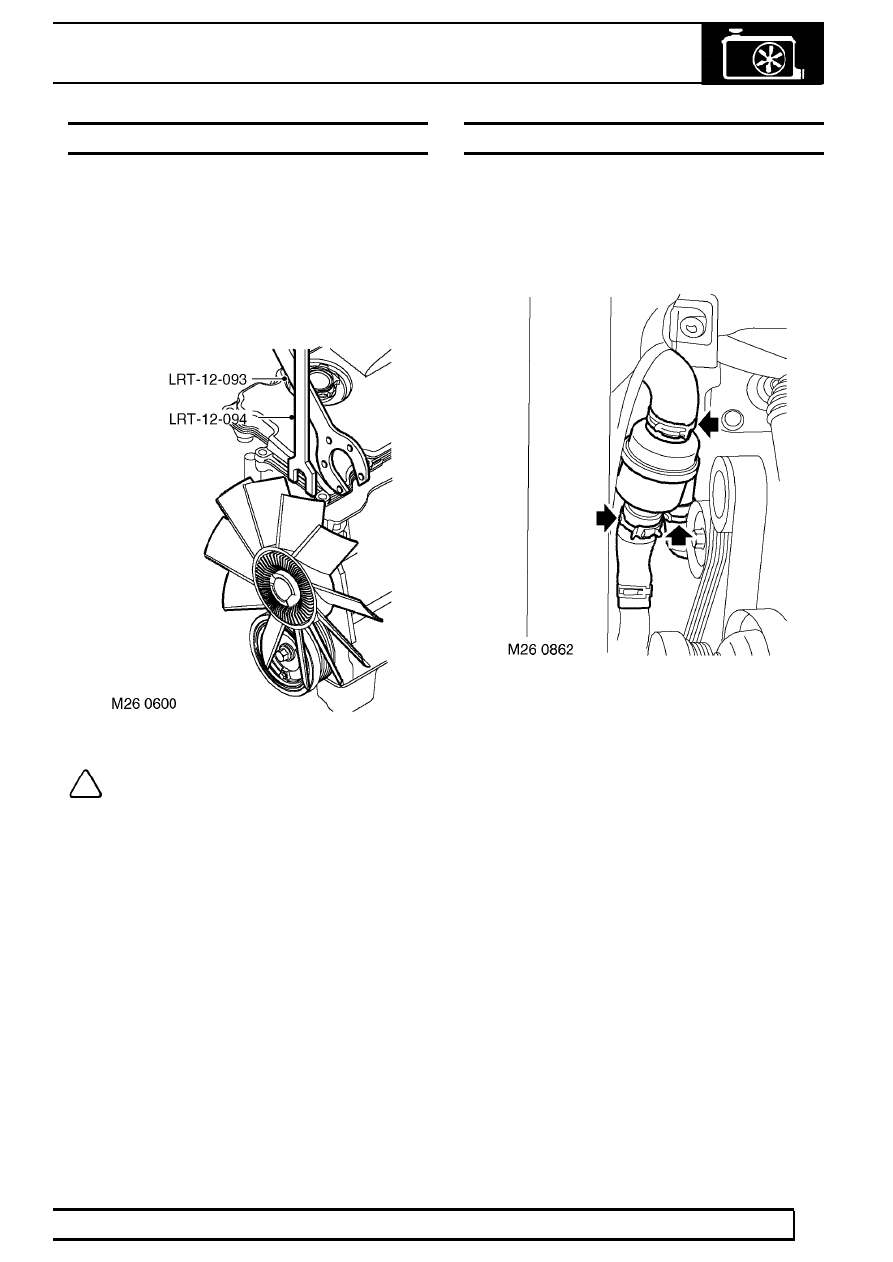
NOTE: Thread is RH.
5. Remove cooling fan using LRT-12-093 and
LRT-12-094.
Refit
6. Position cooling fan and tighten using
LRT-12-093 and LRT-12-094.
7. Fit cooling fan cowl.
8. Fit engine acoustic cover.
9. Reconnect battery negative lead.
10. Fit battery cover.
THERMOSTAT
Service repair no - 26.45.09
Remove
1. Drain cooling system. See Adjustment.
2. Remove cooling fan. See this Section.
3. Release 3 clips and disconnect coolant hoses
from thermostat.
4. Remove thermostat.
Refit
5. Position thermostat, connect hoses and secure
with clips.
6. Fit cooling fan. See this Section.
7. Fill cooling system. See Adjustment.
Нет комментариевНе стесняйтесь поделиться с нами вашим ценным мнением.
Текст